Method and apparatus of agricultural field seeding

a technology of agricultural field and seeding equipment, applied in the direction of seeding, fertiliser and seeding equipment, planting, etc., can solve the problems of crop quality and yield reduction, delay and reduction, and disastrous consequences

Active Publication Date: 2007-01-09
BOURGAULT INDS
View PDF6 Cites 102 Cited by
  • Summary
  • Abstract
  • Description
  • Claims
  • Application Information

AI Technical Summary

Benefits of technology

[0014]The invention allows for the individual adjustment of the depth of each furrow created by either a fertilizer placement opener or a seed placement opener, allowing an operator of the planting apparatus to tailor a one pass seeding and initial fertilizing of a field to the exact conditions of the field, type of crop that will be seeded.
[0015]A parallel linkage trailing arm can conveniently provide improved consistency of seed furrow depth.

Problems solved by technology

In addition to developing machines that allow seeding alone, a lot of effort and development has gone into developing machines that allow the placement of fertilizer in the soil at the same time the seeding is being done.
However, fertilizer that is placed too near the seed can damage the seed and cause delay and reductions in emergence of the crop and can even cause a reduction in the quality and yield of a crop, particularly with more sensitive seeds, in particular soil types and in dry soil conditions.
Even if placing the fertilizer too close to the seed only causes delays in the crop maturing, an early frost before the crop has been harvested can have disastrous consequences to the crop.
The drawback of these types of assemblies is that in certain soil & moisture conditions, for example drier clay soils that tend to lump, it is very difficult to achieve separation of seed and fertilizer when the seed and fertilizer rows are in such close proximity.
However, this system uses the same type of assemblies for depositing both seed and fertilizer and does not allow independent adjustment of the seed placement openers nor does it allow independent depth control of each seed assembly during operation.

Method used


Image

  • Method and apparatus of agricultural field seeding
  • Method and apparatus of agricultural field seeding
  • Method and apparatus of agricultural field seeding

Examples


Embodiment Construction

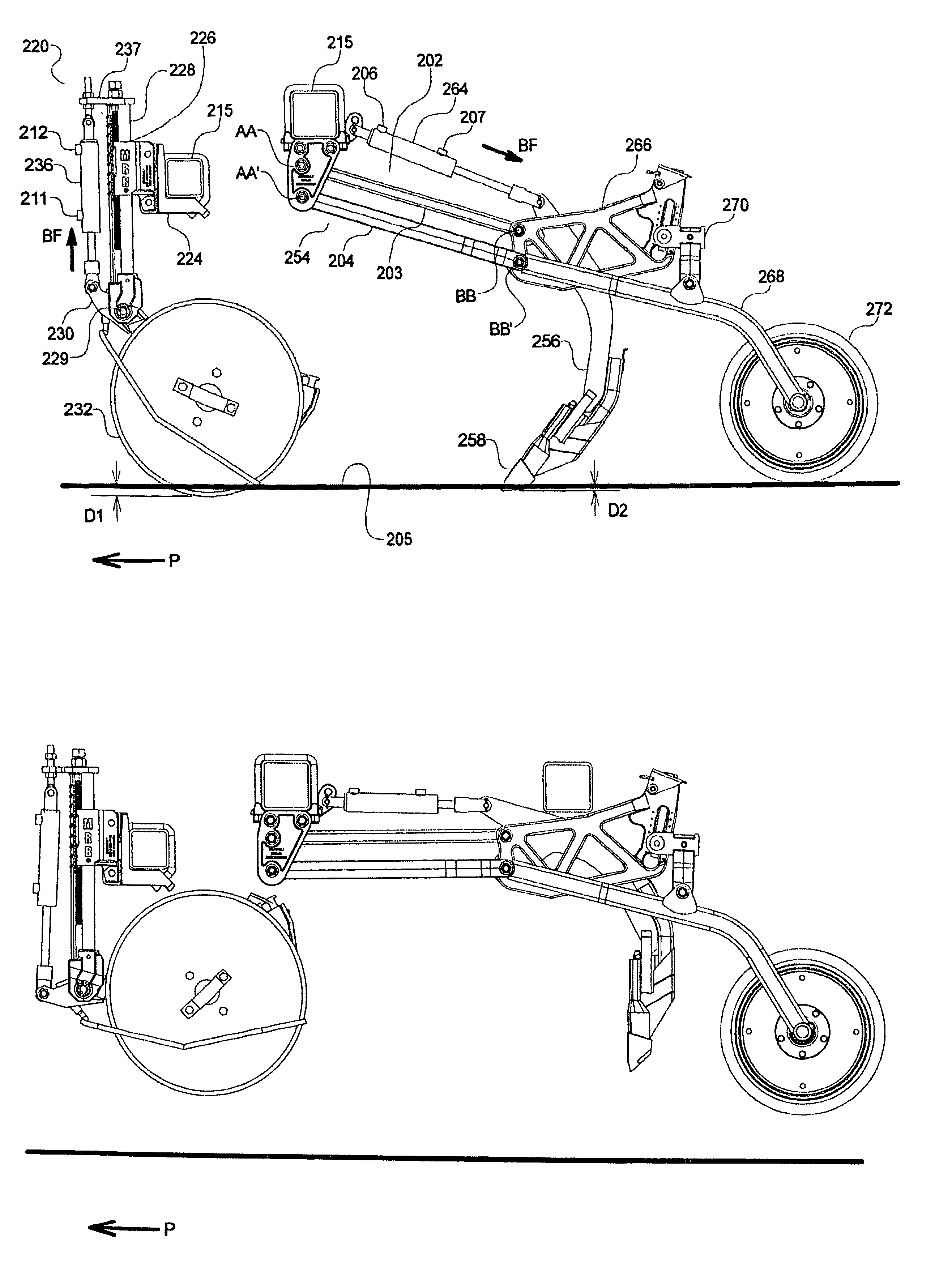
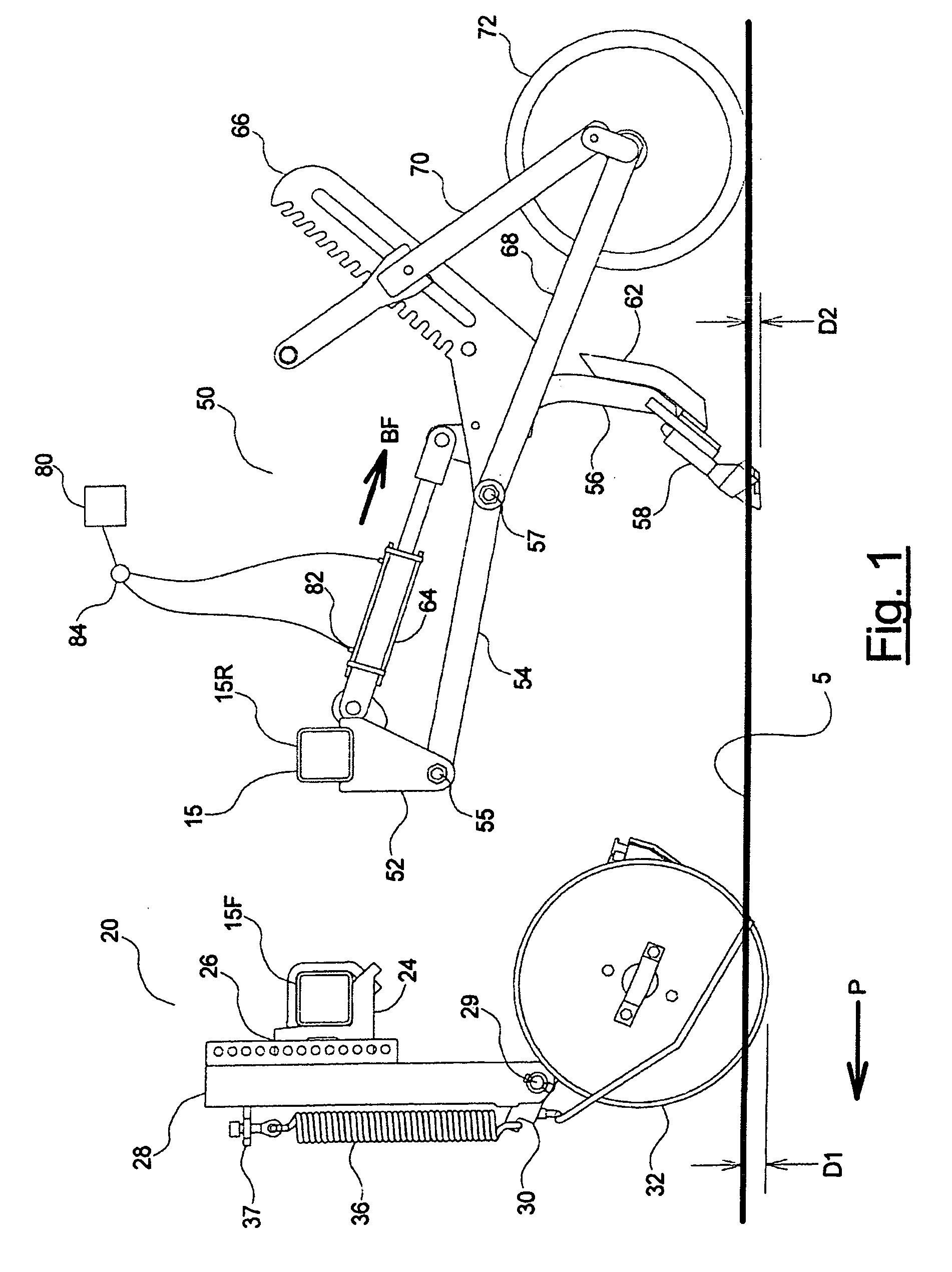
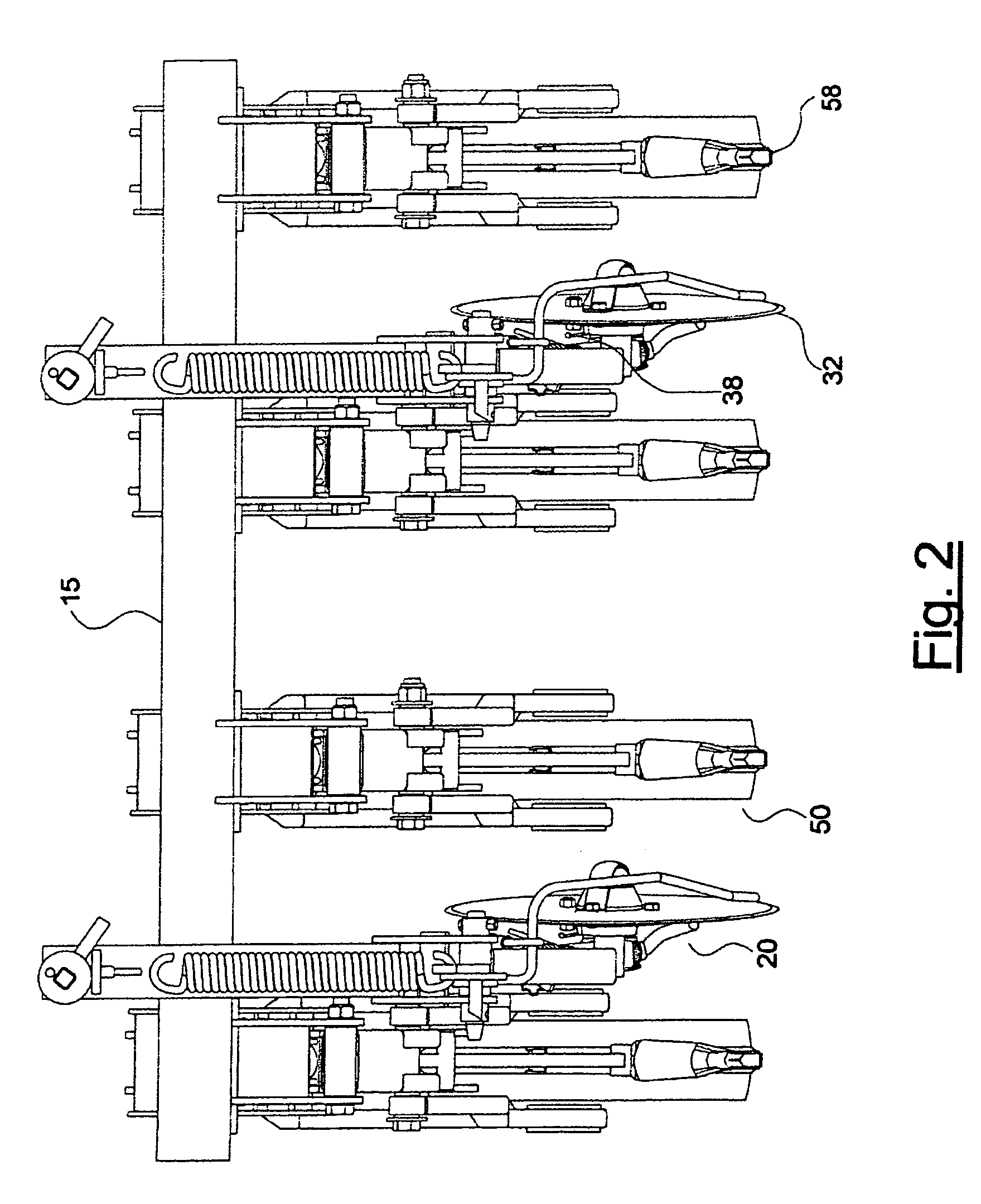
[0026]FIG. 1 illustrates a side view of a fertilizer assembly 20 and a seed assembly 50, used in conjunction to seed and fertilize a field in one pass. FIGS. 2 and 3 illustrate a number of fertilizing assemblies 20 and seed assemblies 50 attached to a section of a frame 15 of a planting implement apparatus. The frame 15 is mounted to wheels for travel along the ground in an operating travel direction P.

[0027]Referring to FIGS. 1 and 2, fertilizer assembly 20 comprises a mounting bracket 24 attached to the frame 15. The mounting bracket 24 is connected to an elongate member 28 through a height adjustable connection 26. A disc bracket 30 is pivotally connected to the lower end of the elongate member 28 with a disk bracket pin 29, and a disc 32 is rotatably mounted to the disc bracket 30. As can be seen in FIG. 2, the disc 32 is oriented at an angle to the operating travel direction P. This angling of the disc 32 creates a fertilizer furrow in a ground surface 5 when the fertilizer pla...


PUM


Abstract

A seeding and fertilizing apparatus comprises a plurality of seed assemblies each comprising a trailing arm pivotally connected at a front end thereof to the frame and a packer wheel rotatably attached to rear end thereof. A seed knife is attached to the trailing arm ahead of the packer wheel which rolls along the seed furrow created by the knife. A vertical position of the knife with respect to the packer wheel is adjustable, and a bias device is operative to exert a downward bias force on the trailing arm. A plurality of fertilizer assemblies each comprises a fertilizer disc rotatably mounted to the frame such that a vertical position of the disc with respect to the implement frame is adjustable. The seed assemblies and fertilizer assemblies are oriented laterally such that each fertilizer furrow is located between adjacent seed furrows.

Description

[0001]This invention relates to agricultural implements and more specifically to a seeding apparatus for one pass seeding and fertilizing.BACKGROUND OF THE INVENTION[0002]Over the years, global competitiveness in agricultural grains markets and economic pressures on individual grain producers have driven farmers to utilize seeding equipment that provides the greatest possible economy of purchase, operation and maintenance. Equally, farmers have sought equipment that optimizes the potential for crop yields by providing accurate seeding depth, optimizing seed / soil contact, preserving soil moisture, and minimizing soil disturbance which promotes weed growth.[0003]Seeding machines have been developed that allow the placement of seed in a field with minimum tilling or even no tilling. In addition to developing machines that allow seeding alone, a lot of effort and development has gone into developing machines that allow the placement of fertilizer in the soil at the same time the seeding...

Claims


Application Information

Patent Timeline
Patent Type & Authority Patents(United States)
IPC IPC(8): A01C7/00A01C9/00
CPCA01C7/203A01C7/06A01C7/205
Inventor BOURGAULT, GERARDCRESSWELL, MARK
Owner BOURGAULT INDS
Why Eureka
Try Eureka