Method of drilling a borehole into an earth formation

a technology of earth formation and drilling method, which is applied in the direction of drilling machine and method, borehole/well accessories, chemistry apparatus and processes, etc., can solve the problems of acidizing and normally inefficient backflow,

Inactive Publication Date: 2007-01-09
SHELL OIL CO
View PDF7 Cites 10 Cited by
  • Summary
  • Abstract
  • Description
  • Claims
  • Application Information

AI Technical Summary

Benefits of technology

[0009]In a preferred embodiment the magnetic field source includes at least one of a permanent magnet and an electromagnet. In case of a permanent magnet, it is preferred that the magnet is enclosed in a removable case of a suitable material which prevents, or suppresses, the magnetic field induced by the magnet outside the case. Remote control means can be used to remove the case from the magnet. Suitably step a) comprises inserting a magnetic rheological fluid (MRF) into the borehole. Such fluid contains suspended magnetisable particles (e.g. iron particles 1–100 μm) which allow the rheological behaviour of the fluid to be controlled through the application of a magnetic field. Before application of the magnetic field, the particles are randomly arranged. After application of such field the particles become aligned in the direction of the field thereby creating an attractive force between the particles resulting in a kind of network.

Problems solved by technology

Back flowing is normally inefficient because the flow rate is generally too low to remove the filter-cake layer, especially for long horizontal wellbore sections.
Acidizing also is generally inefficient because once the acid has dissolved a portion of the filter-cake layer, the remaining acid tends to enter the formation at the location of the removed portion.

Method used


Image

  • Method of drilling a borehole into an earth formation
  • Method of drilling a borehole into an earth formation

Examples


Embodiment Construction

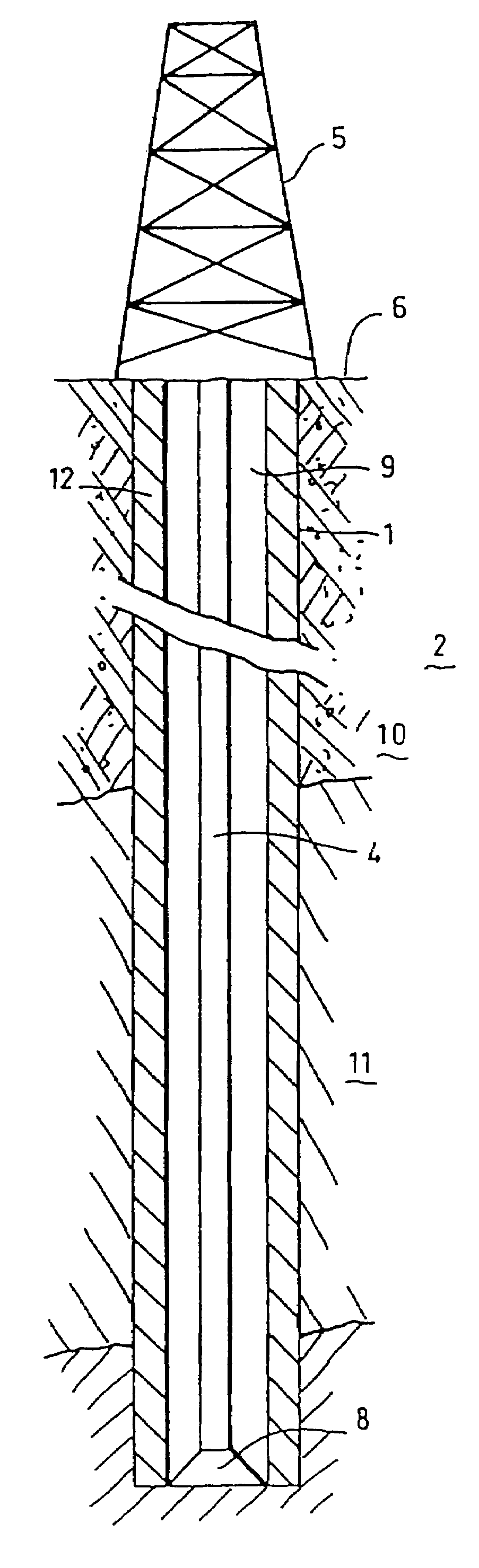
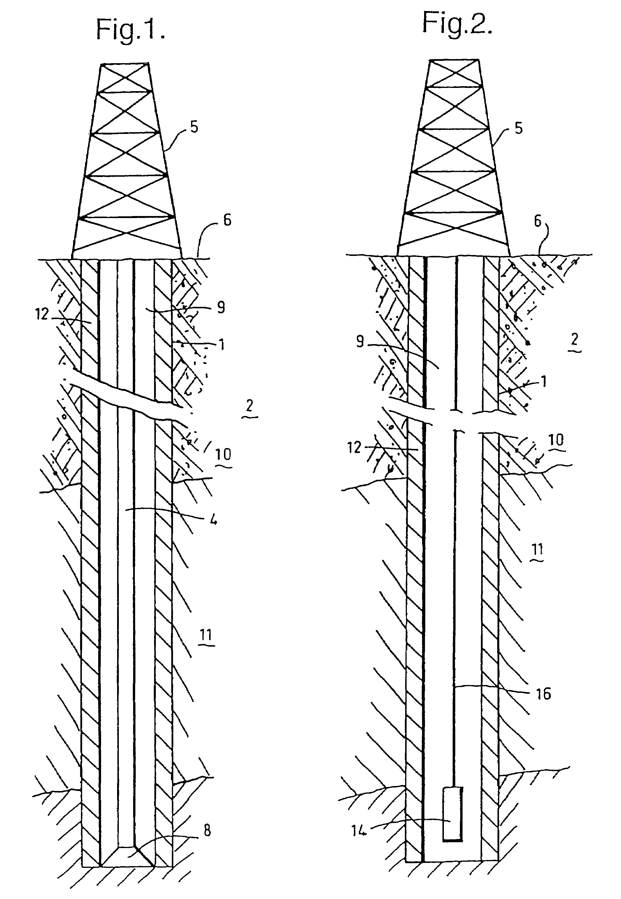
[0013]Referring to FIG. 1 there is shown a borehole 1 drilled into an earth formation 2 using a drill string 4 extending from a drilling rig 5 located at surface 6, the drill string being provided with a drill bit 8 at the lower end thereof. The borehole is filled with a body of drilling fluid 9. The earth formation 2 includes an overburden zone 10 and a hydrocarbon fluid bearing zone 11, the borehole 1 passing through both zones 10, 11. A filter-cake layer 12 is present at the wall of the borehole, which filter-cake layer 12 serves to limit outflow of drilling fluid into the earth formation. The filter-cake layer 12 includes solid magnetisable particles (not shown) and a binding agent for binding the particles to each other, which solid particles substantially block the pores of the formation at the borehole wall. The solid particles of the filter-cake layer 12 in the borehole section traversing the overburden zone 10 are conventional particles for forming a filter-cake layer, wher...


PUM

PropertyMeasurementUnit
magnetic forcesaaaaaaaaaa
magnetic fieldaaaaaaaaaa
ferromagneticaaaaaaaaaa

Abstract

A method of drilling a borehole in an earth formation wherein a plurality of selected solid magnetisable particles is inserted into the borehole, the particles being susceptible of forming a filter cake layer at the borehole wall and being made of a material susceptible of being exposed to magnetic forces when subjected to a magnetic field. A section of the borehole is drilled, and at least part of the filter-cake layer is removed from the wall of the drilled borehole section by inducing a selected magnetic field in the borehole. The magnetic field exerts magnetic forces to the particles, thereby withdrawing the particles from the wall.

Description

CROSS REFERENCE TO RELATED APPLICATION[0001]The present application is a U.S. national stage application under USC § 371 of PCT / EP02 / 12894 filed 18 Nov. 2002, which claims priority of U.S. provisional application 60 / 333,099 filed 19 Nov. 2001.FIELD OF INVENTION[0002]The present invention relates to a method of drilling a borehole in an earth formation, the borehole containing a body of drilling fluid.BACKGROUND OF THE INVENTION[0003]During drilling of wellbores it is common practice to form a filter-cake layer at the borehole wall to limit outflow of drilling fluid into the earth formation surrounding die wellbore. Included solid particles in the drilling fluid which block the pores of the earth formation at the borehole wall, conventionally forms the filter-cake layer. A polymer is furthermore included in the drilling fluid for the purpose of binding the particles to each other. The filter-cake is created by limited leak-off of drilling fluid into the earth formation. When producti...

Claims


Application Information

Patent Timeline
Patent Type & Authority Patents(United States)
IPC IPC(8): E21B7/00E21B37/00C09K8/03C09K8/52
CPCC09K8/032E21B37/00C09K8/52
Inventor EIGNER, MANFRED RUDOLF PAULNEUSTADT, BEATRICESCHOUTEN, JEANETTE CAROLINE
Owner SHELL OIL CO
Why Eureka
Try Eureka