Magnetically-coupled actuating valve assembly

a technology of actuating valves and magnets, which is applied in the direction of valve details, valve arrangement, valve operating means/releasing devices, etc., can solve the problems of difficult control of knee joint operation, poor control of simple artificial knee joints, and inability to walk well for amputees, so as to achieve the effect of reducing the risk of leakage and/or fire, and ensuring the safety of the ampu

Active Publication Date: 2007-01-09
WILLOWWOOD GLOBAL LLC
View PDF5 Cites 34 Cited by
  • Summary
  • Abstract
  • Description
  • Claims
  • Application Information

AI Technical Summary

Benefits of technology

[0007]The present invention overcomes the aforementioned deficiencies by allowing a drive motor to be magnetically coupled to a valve body portion of a valve assembly through a separating wall residing therebetween. As the drive motor is not physically coupled to the valve body, the drive motor can be isolated from the valve body and from the working fluid of the valve assembly without the need for seals or other leak prone elements. Consequently, the risk of leakage and / or fire is substantially eliminated and the drive motor may be operated at maximum power and efficiency.
[0008]One embodiment of the present invention employs a pair of magnets to transmit torque from a drive motor to a valve body portion of the valve assembly. Each magnet is preferably a disk-shaped magnet that has been magnetized across its diameter, such that the pair of magnets is attracted into a specific orientation, but will repel each other under any other orientation. In this embodiment, rotation of the valve body is converted into linear movement by its threaded engagement with a stationary element—thereby greatly reducing any inaccuracies that may occur due to the use of a non-physically coupled linkage.

Problems solved by technology

Such simplistic artificial knee joints are problematic, however.
For example, failure to fully swing the lower leg portion forward during the extension portion of the gait cycle can result in instability, as the knee joint may bend undesirably under the amputee's weight.
Such knee joint operation can be very difficult for the amputee to control—especially as energy (and momentum) builds up during the gait cycle.
Prosthetic limbs employing such damping cylinders are an improvement over earlier limbs that used only undamped knee joints, however, they generally only allowed the amputee to walk well at one speed.
One problem with using such a valve assembly arises, however, due to the high working fluid pressures that are often present in the damping cylinder(s) that are controlled by the valve assemblies.
Because of the high working fluid pressures within the housing, these seals are prone to leakage, which can be quite problematic when the cylinder is used with a prosthetic limb.
And, locating a drive motor or other powered actuator within the valve body does not overcome the aforementioned problem, as a seal must still be used around the wiring providing power thereto.
Additionally, locating a drive motor in the working fluid generally results in reduced motor power and efficiency and, depending on the particular working fluid involved, may create a fire hazard.

Method used


Image

  • Magnetically-coupled actuating valve assembly
  • Magnetically-coupled actuating valve assembly
  • Magnetically-coupled actuating valve assembly

Examples


Embodiment Construction

)

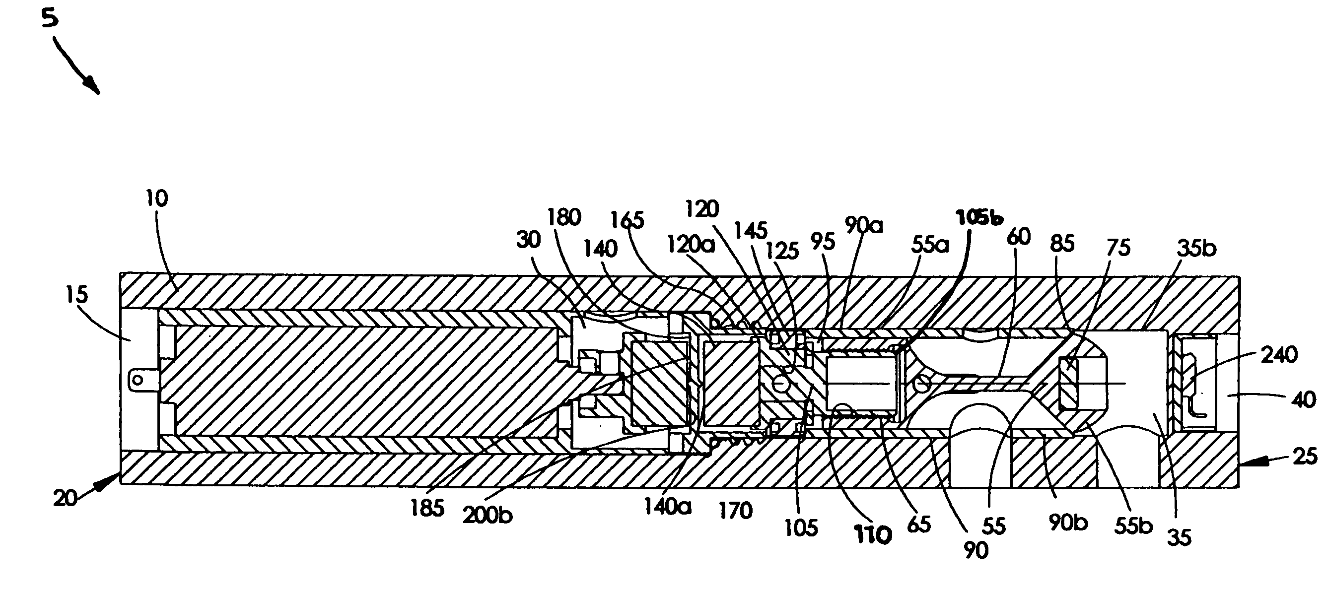
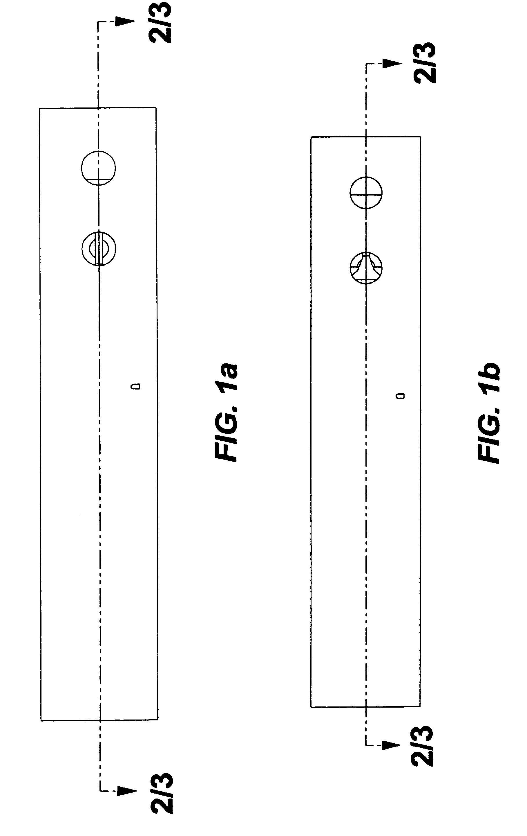
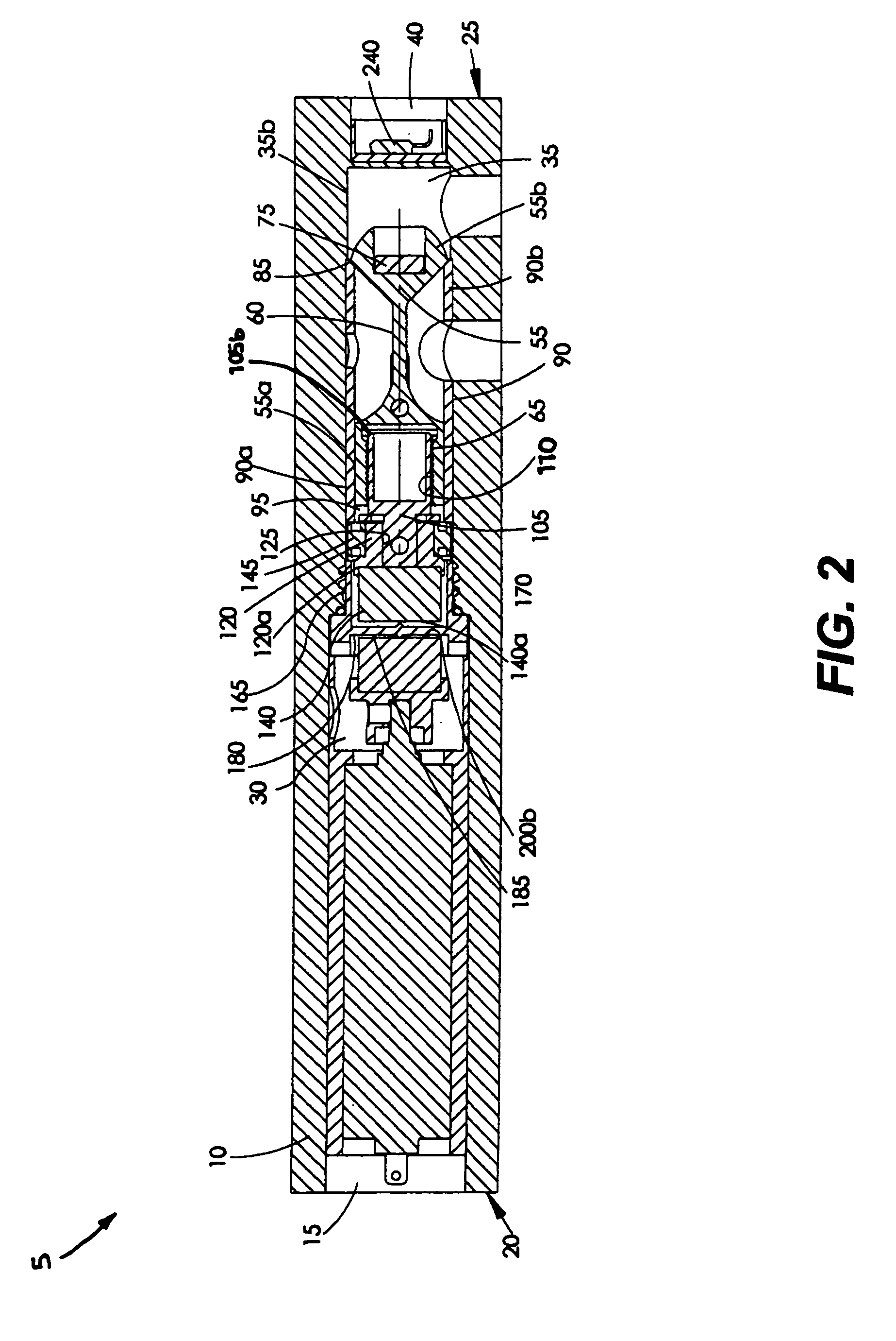
[0021]One embodiment of a magnetically-coupled valve assembly 5 for an electronically controlled prosthetic knee can be seen in FIGS. 1–4. As shown in FIGS. 1–4, the valve assembly 5 resides within a housing 10. It should be understood that the housing 10 depicted in FIGS. 1–4 will typically consist of a portion of a cylinder housing to which the valve assembly 5 is installed (see FIG. 5). However, it is also possible that the valve assembly 5 may have its own housing (as illustrated in FIGS. 1–4), which may be of various cross-sectional shape. The housing 10 may be made of various materials of sufficient strength, but is preferably constructed of a metallic material such as steel, aluminum, or titanium.

[0022]As can be best observed by reference to FIGS. 2–4, a central aperture 15 extends into the interior of the housing 10 from a first (proximal) end 20 thereof. The central aperture 15 of this embodiment is of varying diameter for accommodating the unique components of the valve a...


PUM


Abstract

A magnetically-coupled actuating valve assembly. The actuating valve can be used to control the action of an actuator, such as a hydraulic or pneumatic cylinder. The valve assembly is especially well-suited to use with a damping cylinder of an electronically controlled prosthetic knee. A drive motor is coupled to and actuates a valve body portion of the assembly by means of magnetic attraction and, therefore, the valve assembly operates without the need to physically couple the drive motor to the valve body. The design of the present invention can reduce or eliminate working fluid leaks typically associated with a physical coupling. The design of the present invention may also obviate the need to submerge the drive motor in the working fluid, which typically reduces motor efficiency and may pose a fire hazard.

Description

BACKGROUND OF THE INVENTION[0001]The present invention is directed to a magnetically-coupled actuating valve assembly for use in controlling an actuator, such as a hydraulic or pneumatic actuator. More specifically, the present invention is directed to an actuating valve assembly having a valve body that is magnetically coupled to a drive motor, thereby allowing the drive motor to be isolated from pressurized fluid passing through the valve assembly.[0002]While it is to be understood that an actuator incorporating the actuating valve assembly of the present invention may be used in a variety of devices, the actuating valve assembly is particularly well-suited to use in an electronically controlled actuator for a prosthetic limb. More particularly, the valve assembly of the present invention is especially compatible with a damping cylinder of an electronically controlled prosthetic knee. Such a damping cylinder can be used to control (damp) the flexion and extension phases of knee mo...

Claims


Application Information

Patent Timeline
Patent Type & Authority Patents(United States)
IPC IPC(8): F16K31/04
CPCF16K31/082A61M39/22
Inventor TAYLOR, MARC D.HAYNES, MICHAEL L.
Owner WILLOWWOOD GLOBAL LLC
Why Eureka
Try Eureka