Therapeutic electrolysis device

a technology of electrolysis device and electrolysis device, which is applied in the field of electrolysis device, can solve the problems of inefficient electrolysis device, large electrical power requirement of the device, and relatively small shift in the number of positive ions present, and achieve the effect of ionizing water

Active Publication Date: 2007-01-09
ROBERT E MORONEY
View PDF29 Cites 12 Cited by
  • Summary
  • Abstract
  • Description
  • Claims
  • Application Information

AI Technical Summary

Benefits of technology

[0009]The present invention generally includes an ionizer unit having two integral plate assemblies, a control unit, and a power conduit. Each of the plate assemblies has a terminal portion. In accordance with an embodiment of the present invention, the first of the two plate assemblies has an odd number of plates while the second plate assembly has an even number of plates. In accordance with another embodiment of the present invention, the first and second plate assemblies have different surface areas. To create the electric field necessary to effectively ionize water, the plate assemblies are interposed such that plates of the plate assembly with an odd number of plates is separated by a gap from plates of the plate assembly with an even number of plates. In order to maintain the gaps between the plates, the plate assemblies may be held by or within a frame. Each plate assembly includes an electrical terminal that is interconnected to a corresponding terminal of the control unit by a conduit. In accordance with still another embodiment of the present invention, the plate assemblies are formed from integral pieces of material, removing the need to form interconnections between the plates of a given plate assembly during manufacture.

Problems solved by technology

Existing electrolysis devices for use in connection with therapeutic applications are inefficient.
In particular, such devices require a relatively large amount of electrical power, while producing a relatively small shift in the number of positive ions present in the water relative to the number of negative ions present in the water.
In addition, existing devices have been unreliable.
In particular, such devices have suffered from failures in connections between components made at locations that are under water when the device is in operation.
However, no provision is generally made for automatically alternating between producing a preponderance of negative ions and producing a preponderance of positive ions.

Method used


Image

  • Therapeutic electrolysis device
  • Therapeutic electrolysis device
  • Therapeutic electrolysis device

Examples


Embodiment Construction

[0023]In accordance with the present invention, a method and apparatus for providing a therapeutic electrolysis device are disclosed.

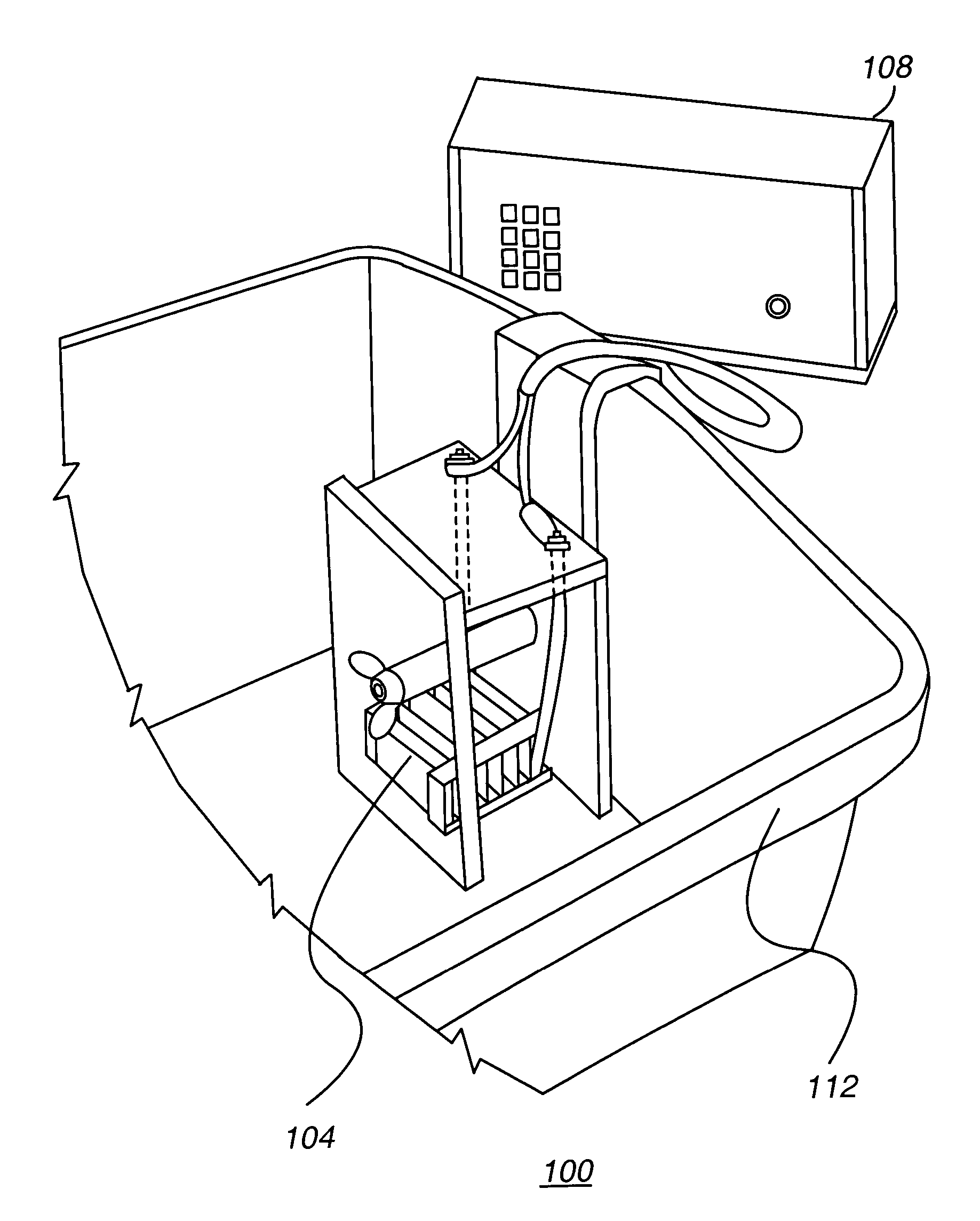
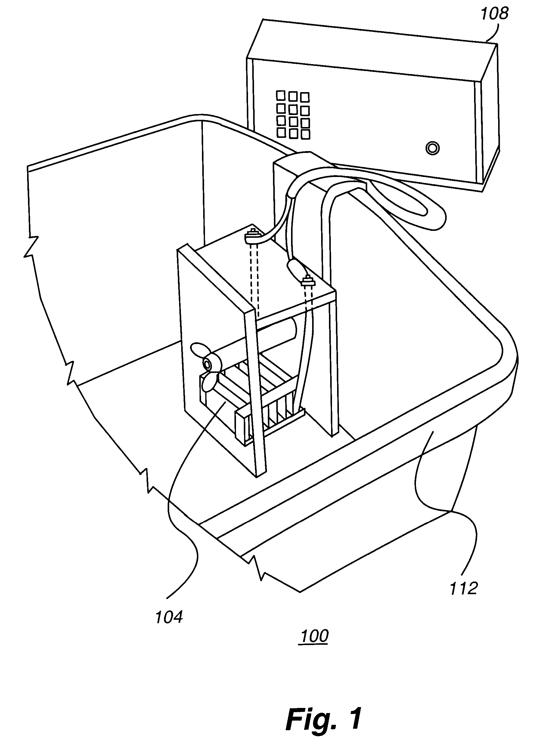
[0024]In FIG. 1, a therapeutic electrolysis system 100 in accordance with an embodiment of the present invention is depicted. In general, the therapeutic electrolysis system includes an ionizer unit 104 interconnected to a control unit 108. In addition, the therapeutic electrolysis system 100 includes a basin 112. Furthermore, in operation, the therapeutic electrolysis system 100 utilizes water 236 (see FIG. 2) held in the basin 112.

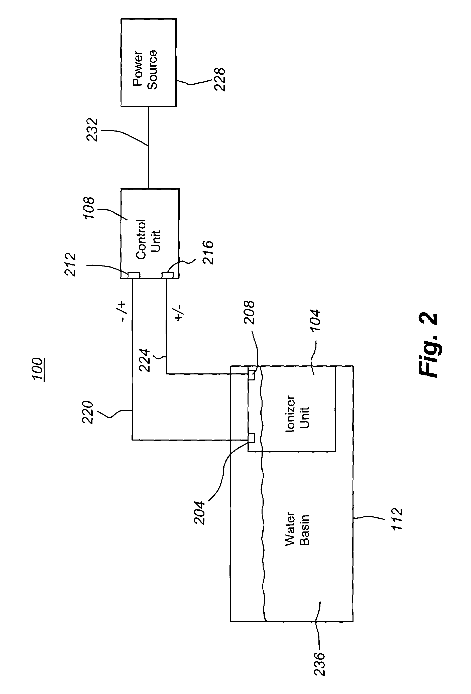
[0025]FIG. 2 depicts a therapeutic electrolysis system 100 in accordance with an embodiment of the present invention in block diagram form. As can be seen in FIG. 2, the ionizer unit 104 includes a first electrical terminal 204, which is interconnected to a first switchable electrical terminal 212 on the control unit 108 by a first electrical conductor or conduit 220. Similarly, the second electrical terminal 208 of the ion...


PUM

PropertyMeasurementUnit
conductiveaaaaaaaaaa
widthaaaaaaaaaa
surface areaaaaaaaaaaa

Abstract

An electrolysis device is provided. The electrolysis device includes an ionizer unit having first and second plate assemblies that each provide a different surface area that is contacted by water when the unit is in use. The plate assemblies may each provide a different surface area by providing a different number of plates. The plate assemblies are formed from integral pieces of material, to enhance the reliability of the device. The present invention further provides a control unit programmed to provide an output to the ionizer unit that varies in polarity over time.

Description

CROSS REFERENCE TO RELATED APPLICATIONS[0001]This application claims the benefit of U.S. Provisional Patent Application Ser. No. 60 / 366,773, filed Mar. 22, 2002, the entire disclosure of which is incorporated by reference herein.FIELD OF THE INVENTION[0002]The present invention relates to an electrolysis device for use in connection with therapeutic purposes. In particular, the present invention relates to a device capable of efficiently ionizing water for therapeutic uses.BACKGROUND OF THE INVENTION[0003]Electrolysis involves ionizing water by passing an electrical current through water. When water is ionized, the individual water molecules are split into their constituent elements, namely hydrogen ions (H+) and hydroxy ions (OH−).[0004]By creating a preponderance of either negative ions or positive ions in water, desirable effects can be realized. For example, it is believed that charged particles can be drawn from the body by placing a body part, such as the feet, in a water bath...

Claims


Application Information

Patent Timeline
Patent Type & Authority Patents(United States)
IPC IPC(8): C02F1/461A61H33/14
CPCA61H33/14A61H2033/141
Inventor BECKER, HANSMORONEY, ROBERT E.
Owner ROBERT E MORONEY
Why Eureka
Try Eureka