
Ultrafast laser system for biological mass spectrometry
a laser system and mass spectrometry technology, applied in the field of mass spectrometry, can solve the problems of incomplete backbone fragmentation, limited application of mass spectrometry and associated methodologies for comprehensive proteome analysis, and inability to have bond-selective control over the site of laser pulse energy absorption, so as to prevent the redistribution of energy and fast fragmentation of ions
- Summary
- Abstract
- Description
- Claims
- Application Information
AI Technical Summary
Benefits of technology
Problems solved by technology
Method used
Image

Examples
Embodiment Construction
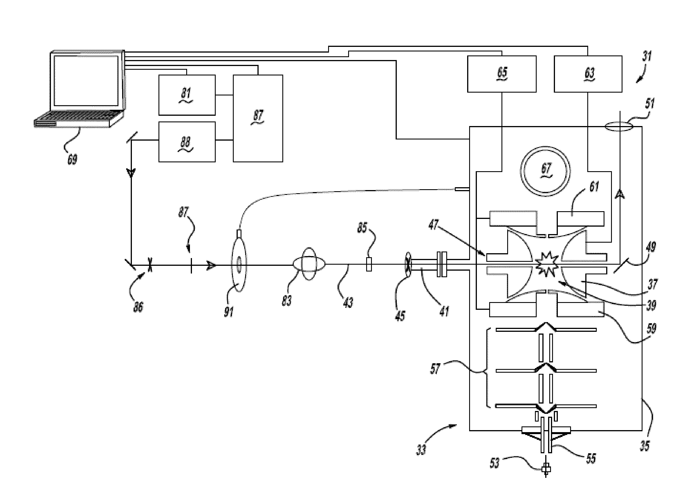
[0038]Referring to FIG. 1, a preferred embodiment of the ultrafast laser system 31 of the present invention includes a 3D ion-trap mass spectrometer 33 (model LCQ Deca XP Plus, Thermo Scientific, San Jose, Calif.) modified using the following specific conditions: a ½″ hole is drilled through the left hand side of a vacuum manifold 35 at a 60° downward angle, in line with the center of a ring electrode 37 of an ion-trap 39, and an aluminum conflat nipple is welded to the manifold. A series of ½″ KwikFlange components are used to construct a vacuum-sealed entrance port 41 for a laser pulse 43, capped with a 1″ diameter fused silica window 45. A 5 mm hole 47 is drilled through ring electrode 37 of the ion-trap, and quartz spacers on either side of the ring electrode are notched to allow clear passage of the laser pulse through the ion-trap. A silver mirror 49, mounted on a custom-cut aluminum block, is then fixed to vacuum manifold 35 on the far side of the trap to direct laser beam pu...
PUM
 Abstract
Description
Claims
Application Information