Membrane filter for water treatment

a membrane filter and filter body technology, applied in the field of membrane filters, can solve the problems of not being able to make any effective contribution to the membrane purification effect, unable to ensure the effect of gasification in the upper region of the fiber bundle, and unable to ensure the availability of sufficient air within the fiber bundl

Inactive Publication Date: 2007-01-09
KOCH SEPARATION SOLUTIONS INC
View PDF3 Cites 26 Cited by
  • Summary
  • Abstract
  • Description
  • Claims
  • Application Information

AI Technical Summary

Benefits of technology

[0009]The invention is based on the task of indicating a membrane filter for water treatment in which effective gasification over the entire length of the fiber bundle is guaranteed, and an effective transport to remove membrane deposits that come loose from the membrane surfaces is assured.
[0010]This task is accomplished, according to the invention, in that the head piece contains an air duct to which the mouth piece that protrudes into the fiber bundle is connected, and that the fibers of the bundle terminate, at their other ends, without being clamped in place, in freely movable manner in the untreated water. The air that exits from the mouth piece flows through the fiber bundle from the inside to the outside, and partially flows away in the lengthwise direction of the capillary membranes. The air feed is preferably supplied intermittently, with the goal of cleaning off cover layers that have formed on the membrane surface during membrane filtration. The air introduction into the fiber bundle, according to the invention, allows surprisingly effective cleaning, independent of the flow velocity of the untreated water. In this regard, the membrane filter according to the invention can also be used in immersion operation.
[0011]The mouth piece possesses a pipe-shaped section, for example, with bores on the circumference, or is structured as a ring gap nozzle, from which the air exits radially or at least with a radial movement component. The air can be introduced into the fiber bundle in targeted manner by means of sizing the length of the mouth piece and by the arrangement of the exit bores or exit nozzles. It also proves to be advantageous if the mouth piece has a kick-back valve that closes if the pressure of the air feed drops.

Problems solved by technology

Effective gasification is no longer guaranteed in the upper region of the fiber bundle.
Sufficient air distribution within the fiber bundle is not guaranteed.
The air is essentially guided along the outside of the membrane bundle, with the untreated water flow, and does not make any effective contribution to the membrane purification effect.

Method used


Image

  • Membrane filter for water treatment
  • Membrane filter for water treatment
  • Membrane filter for water treatment

Examples


Embodiment Construction

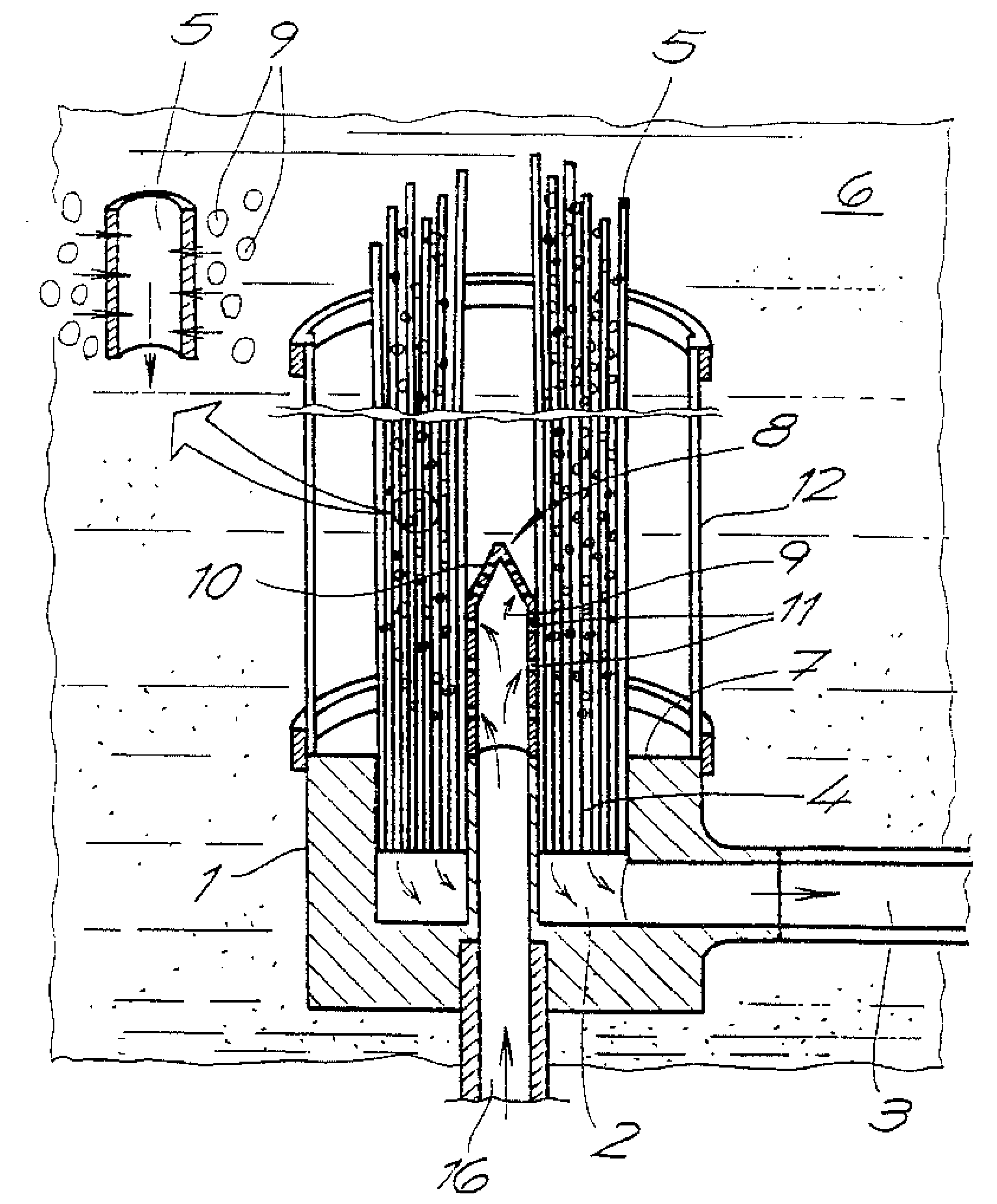
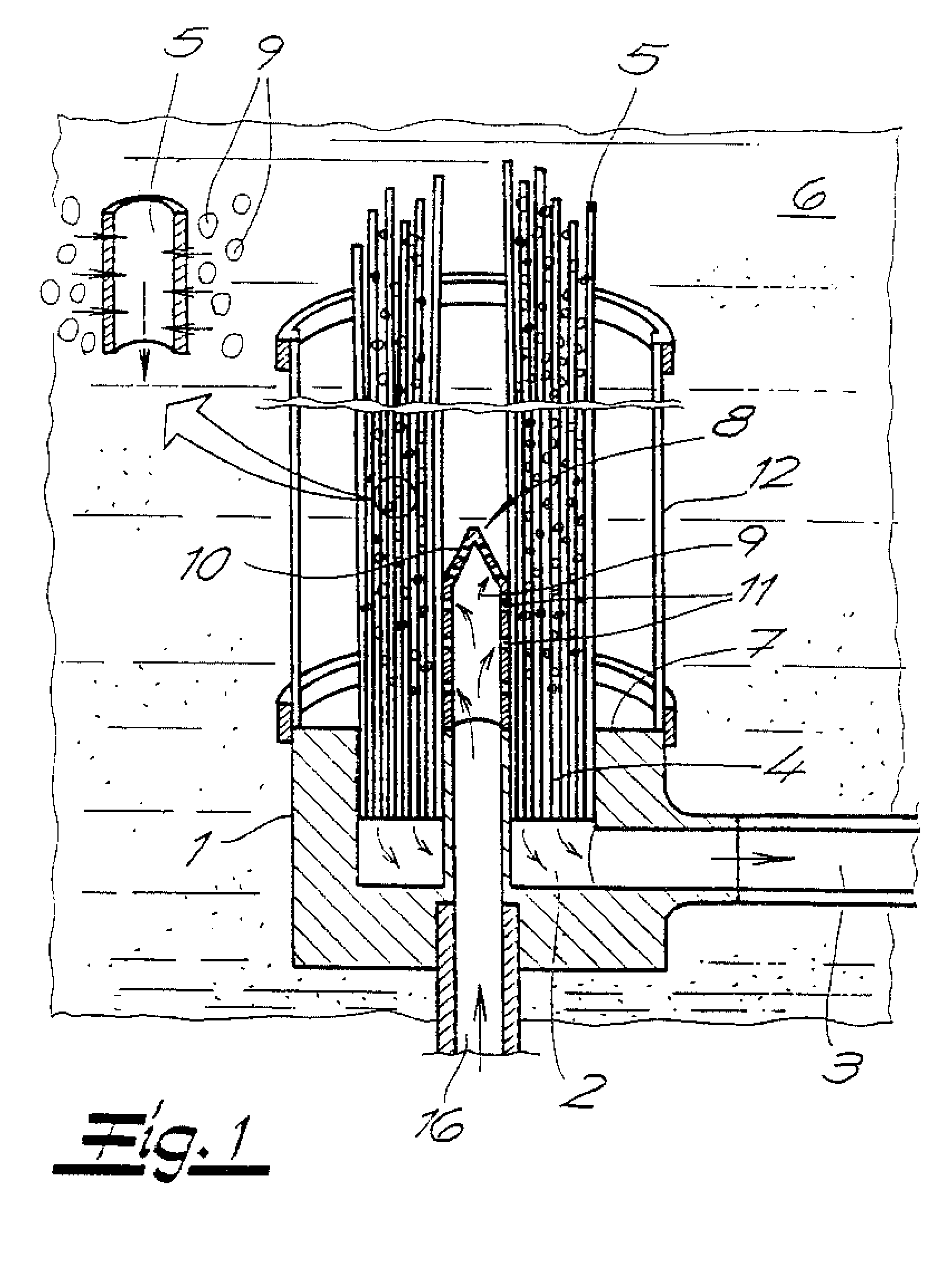
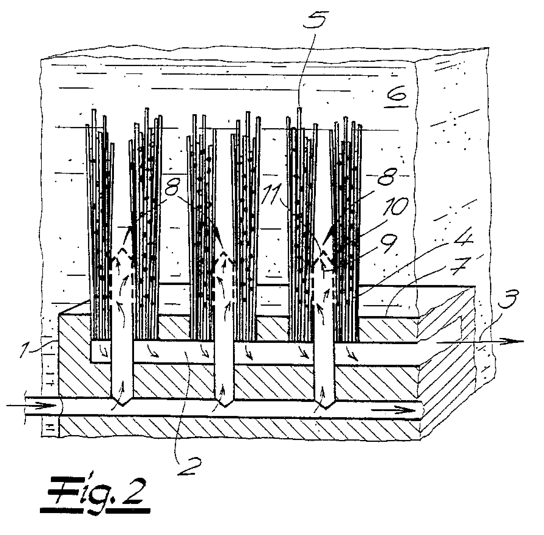
[0016]The fundamental structure of the membrane filters according to the invention as shown in the figures includes a head piece 1, which has a permeate collecting chamber 2 with a permeate outlet 3, and at least one fiber bundle 4 made up of capillary membranes 5, which are sealed at one end and are secured into the head piece 1 at their other end, with an open end towards the permeate collecting chamber 2. The capillary membranes 5 are preferably ultrafiltration membranes or microfiltration membranes, the diameter of which is less than 5 mm. Preferably, the capillary membranes possess a diameter between 0.5 and 3 mm. The capillary membranes 5 are surrounded by the untreated water 6 that is to be treated. Filtration takes place on the basis of a trans-membrane pressure difference, which can be generated by means of an excess pressure on the untreated water side and / or by a reduced pressure on the permeate side. The clarified liquid flows off through the lumen of the capillary membr...


PUM

PropertyMeasurementUnit
diameteraaaaaaaaaa
diameteraaaaaaaaaa
diameteraaaaaaaaaa

Abstract

The invention relates to a membrane filter for water treatment, comprising a head piece including a permeate collecting chamber with a permeate outlet, and at least one fiber bundle made from capillary membranes, which are secured into the head piece with an end that is open towards the permeate collecting chamber and sealed on the opposite end thereof. The head piece contains an air duct to which the mouth piece that protrudes into the fiber bundle is connected with at least one air outlet. At its other end, the fiber bundle terminates in freely movable manner in the untreated water.

Description

RELATED APPLICATIONS[0001]This application claims priority to U.S. application Ser. No. 10 / 380,568, filed Aug. 1, 2003 and entitled “Membrane Filter For Water Treatment.” U.S. application Ser. No. 10 / 380,568 having Publication No. US2004 / 0035779 claims priority to PCT / EP2001 / 09788, international filing date of Aug. 24, 2001, which claims priority to German Application No. 10045227.2, filed Sep. 13, 2000, the entire disclosures of each of these documents are hereby incorporated by reference.BACKGROUND[0002]A membrane filter having capillary membranes of the membrane filter that can be used in immersion operation that are clamped between two head pieces at their ends is known from WO 98 / 28066. A gasification device is connected at the one head piece, which is the lower one in operation. The other, upper end contains the permeate collecting chamber. It forms a displacement body, which has the effect of displacing the rising air bubbles towards the outside of the membrane fiber bundle. ...

Claims


Application Information

Patent Timeline
Patent Type & Authority Patents(United States)
IPC IPC(8): B01D63/02B01D63/04B01D65/02B01D65/08C02F1/44
CPCB01D63/024B01D63/04B01D63/043B01D65/02B01D65/08C02F1/444C02F2303/16B01D2313/26B01D2315/06B01D2321/12B01D2321/185B01D2313/06C02F1/44B01D63/0241
Inventor VOSSENKAUL, KLAUSSCHAFER, STEFAN
Owner KOCH SEPARATION SOLUTIONS INC
Why Eureka
Try Eureka