Slide case with removable rack

a slide case and slide technology, applied in the field of specimen slide storage containers, can solve the problems of not being able to protect slides in bulk storage containers, not being able to use special handling in most commercial environments, and being unsuitable for such processing, so as to reduce the need and associated costs of removal, the effect of flexible and durable use and simple construction

a slide case and slide technology, applied in the field of specimen slide storage containers, can solve the problems of not being able to protect slides in bulk storage containers, not being able to use special handling in most commercial environments, and being unsuitable for such processing, so as to reduce the need and associated costs of removal, the effect of flexible and durable use and simple construction

US7160514B2Inactive Publication Date: 2007-01-09NEW ERIE SCI LLC

Image

  • Slide case with removable rack
  • Slide case with removable rack
  • Slide case with removable rack

Examples


Embodiment Construction

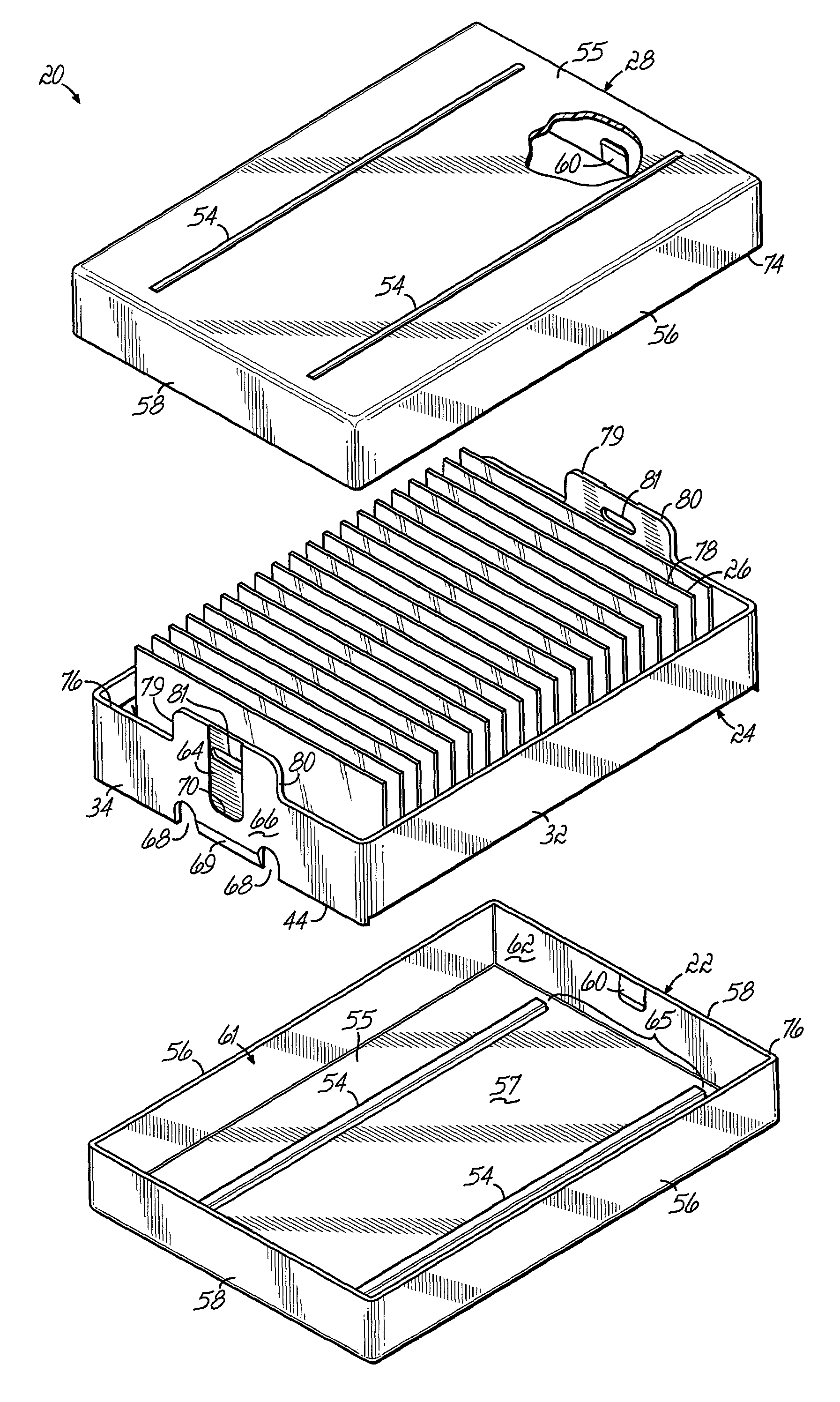
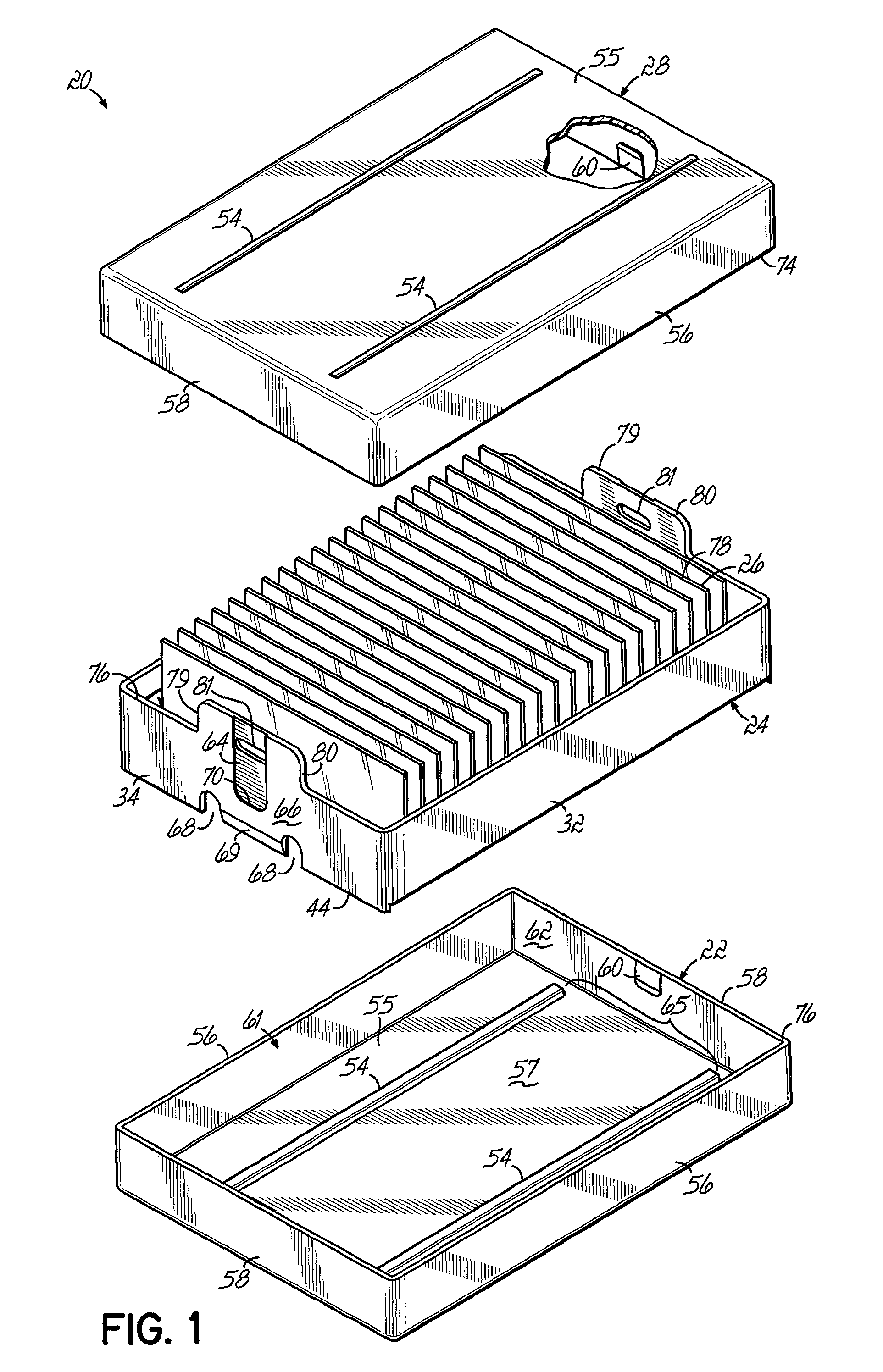
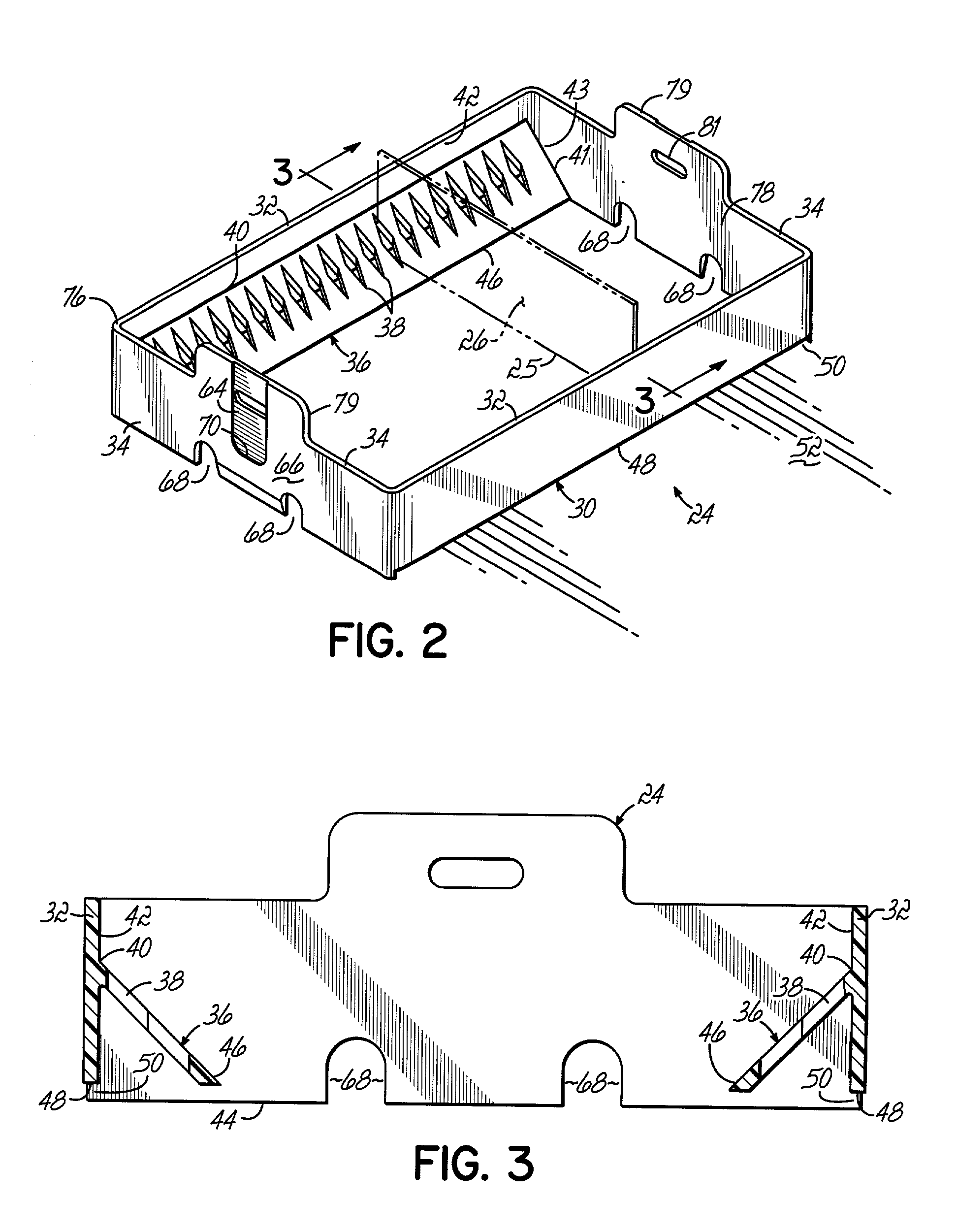
[0018]Referring to FIG. 1, a slide case 20 is comprised of a lower case or base 22 that removably receives and supports a slide rack 24. The rack 24 individually supports and stores a plurality of flat, planar, rectangular slides 26, for example, glass specimen slides often used in laboratories. To facilitate picking up and carrying the rack 24, the rack 24 has handles 79 formed by upward extending tabs 80 and holes 81. An upper case or cover 28 fits over the slide rack 24 and when secured, abuts against the base 22, thereby providing the enclosed slide case 20. Referring to FIG. 2, the rack 24 has a quadrilateral frame 30 with two opposed longitudinally extending side walls 32 and opposed end walls 34. The rack 24 has no bottom or lower wall, and thus, fluids are able to pass through the rack 24. Two opposed support bars 36 are rigidly connected to the sides 32. The support bars 36 have a series of generally diamond shaped openings 38, and each of the openings 38 provides a subjace...


PUM


Abstract

A rack for holding specimen slides. The rack has a frame with opposed support bars having opposed openings for supporting opposite ends of the specimen slides. The support bars have edges connected to sides of the frame, so that the support bars are resiliently deflectable with respect to the frame. The rack of specimen slides is containable in a slide case for purposes of transportation. The slide case has a base with a first latch portion, and the rack has a second latch portion. As the rack is positioned adjacent the base, the first and second latch portions are placed in juxtaposition to releasably secure the rack in the base. A cover is positionable over the base such that the base and cover fully enclose the rack of specimen slides. As the cover is closed over the base, the cover pushes the specimen slides against the opposed support bars, thereby deflecting the support bars and securing the specimen slides in the slide case.

Description

FIELD OF THE INVENTION[0001]This invention relates generally to a container for storing specimen slides and, more particularly, to an improved container for storing and transporting specimen slides.BACKGROUND OF THE INVENTION[0002]There are known storage containers for the bulk storage of frangible sheet material, such as specimen slides. Known containers often have opposed pairs of slots separated by a fixed distance for receiving the slides, and such storage containers have proven satisfactory for storing slides. However, the slides are often subjected to various processes, for example, dipping in liquids and preprocess drying in a centrifuge, but the known storage containers are not suitable for use in such processing. Therefore, the slides must be removed from the storage containers and transferred to other racks that can be used with the preprocessing machines.[0003]In other situations, the slides must be shipped to another location. Known bulk storage containers are not able t...

Claims


Application Information

Patent Timeline
09 Jan 2007
Publication
US7160514B2
IPC
B01L9/00; B65D25/10; B65D85/48; G02B21/34
CPC
B65D25/107; G02B21/34; B65D85/48
Inventors
CHOUINARD, RICHARD J.; COSBY, N. GUY