Method and structure for variable pitch microwave probe assembly

a microwave probe and variable pitch technology, applied in the field of test probes, can solve the problems that the electrical performance of any component, such as a testing probe, is extremely sensitive to changes in shape and dimension, and achieves the effect of improving the test of circuits operating

Inactive Publication Date: 2007-01-09
GLOBALFOUNDRIES INC
View PDF7 Cites 9 Cited by
  • Summary
  • Abstract
  • Description
  • Claims
  • Application Information

AI Technical Summary

Benefits of technology

[0009]However, it is noted that the electrical performance of any component, such as a testing probe, used at the high frequencies inherent in the microwave range is extremely sensitive to changes in shape and dimensions. This is one reason that conventional CPW probes are fixed in pitch since it simplifies the optimization of shape and dimensions.
[0013]Therefore, a need exists for a CPW microwave probe that can be adjusted for various pitches without compromising the electrical performance required to be maintained at these high frequencies.
[0014]Apart from saving the inventory costs of stocking many different probe tip pitches, a probe tip having adjustable pitch would enable quick measurements of many different package and circuit geometries to be made without paying the penalty of fabrication lead time for these probes. Moreover, it is often the case that the long lead time for these probes can represent a more significant economic penalty than the costs of the probes themselves.
[0017]It is another exemplary feature of the present invention to reduce the cost of testing microwave components by providing a test probe that can be adjusted for different test contact pitches, thereby precluding the need to maintain a large inventory of probes having different pitches.
[0021]In a fourth exemplary aspect of the present invention, also described herein is a method of fabricating a micro-coaxial probe assembly, including attaching at least one peripheral probe tip element to an outer wall of a micro-coax assembly having at least one center conductor, the center conductor being extended to serve as an inner probe element for testing a test point, and at least one peripheral probe tip element being attached to the outer wall a predetermined distance from an end of the inner probe element to be used to contact a test point; and incorporating an interface on the outer wall for a mechanism that allows the at least one peripheral probe tip element to be adjusted in separation from the at least one center conductor.
[0022]Thus, the present invention provides a structure and method for improved testing of circuits operating in the microwave region by providing a test probe having an adjustable pitch that maintains the electrical aspects of the interface transition over the adjustable range, thereby providing a universal probe that can be used for different test point pitches.

Problems solved by technology

However, it is noted that the electrical performance of any component, such as a testing probe, used at the high frequencies inherent in the microwave range is extremely sensitive to changes in shape and dimensions.

Method used


Image

  • Method and structure for variable pitch microwave probe assembly
  • Method and structure for variable pitch microwave probe assembly
  • Method and structure for variable pitch microwave probe assembly

Examples


Embodiment Construction

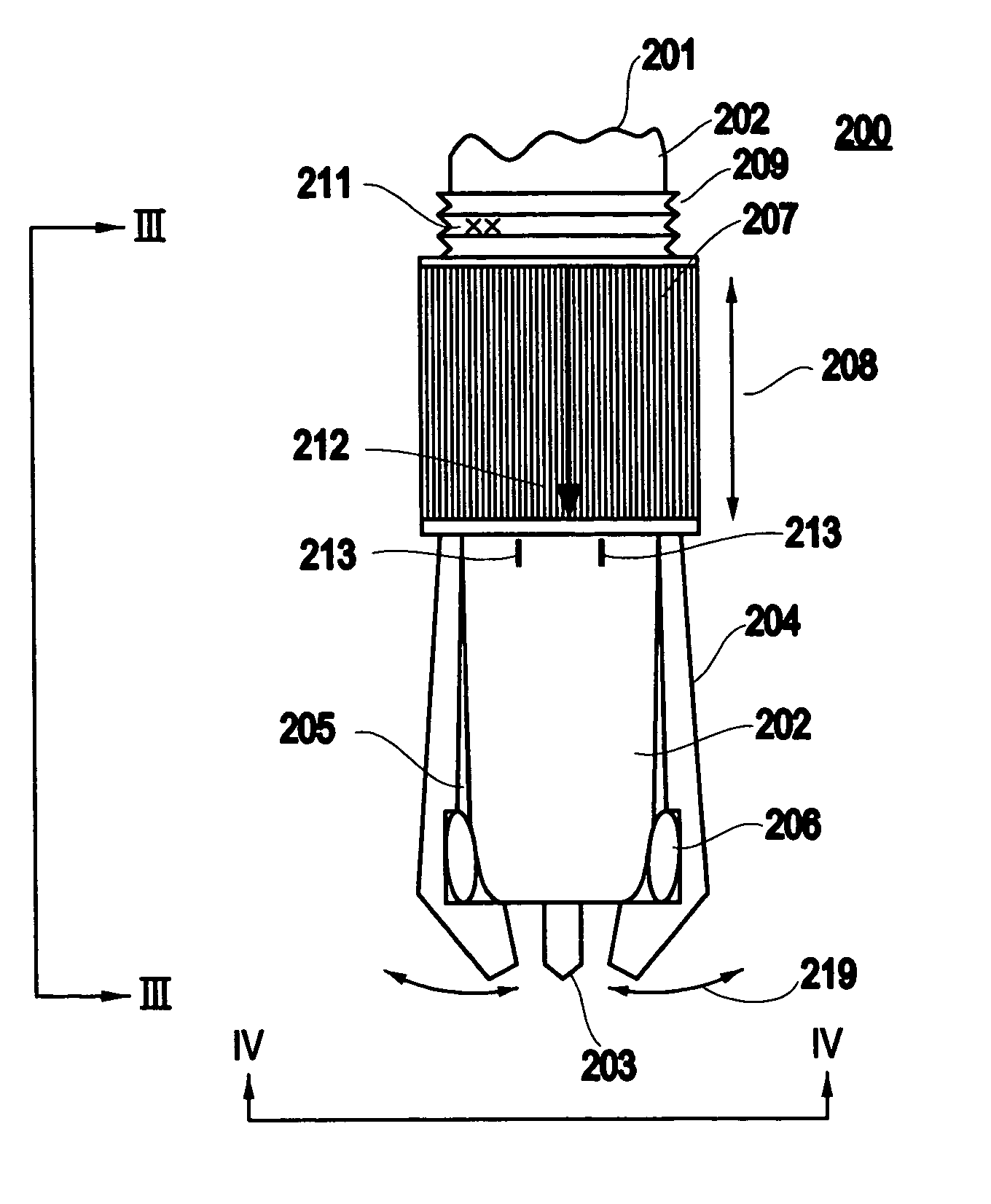
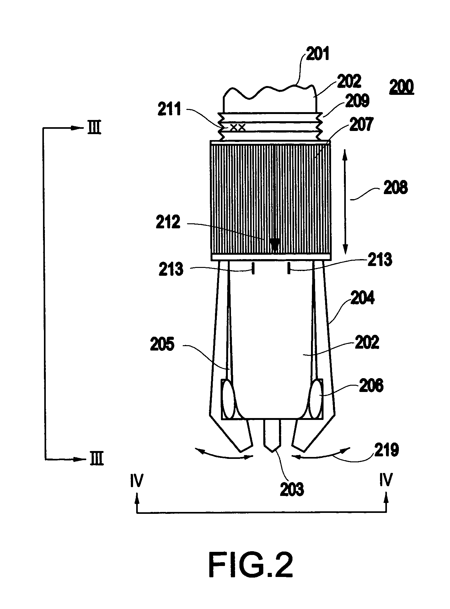
[0030]Referring now to the drawings, and more particularly to FIGS. 2–5, an exemplary embodiment 200 of the present invention will now be described.

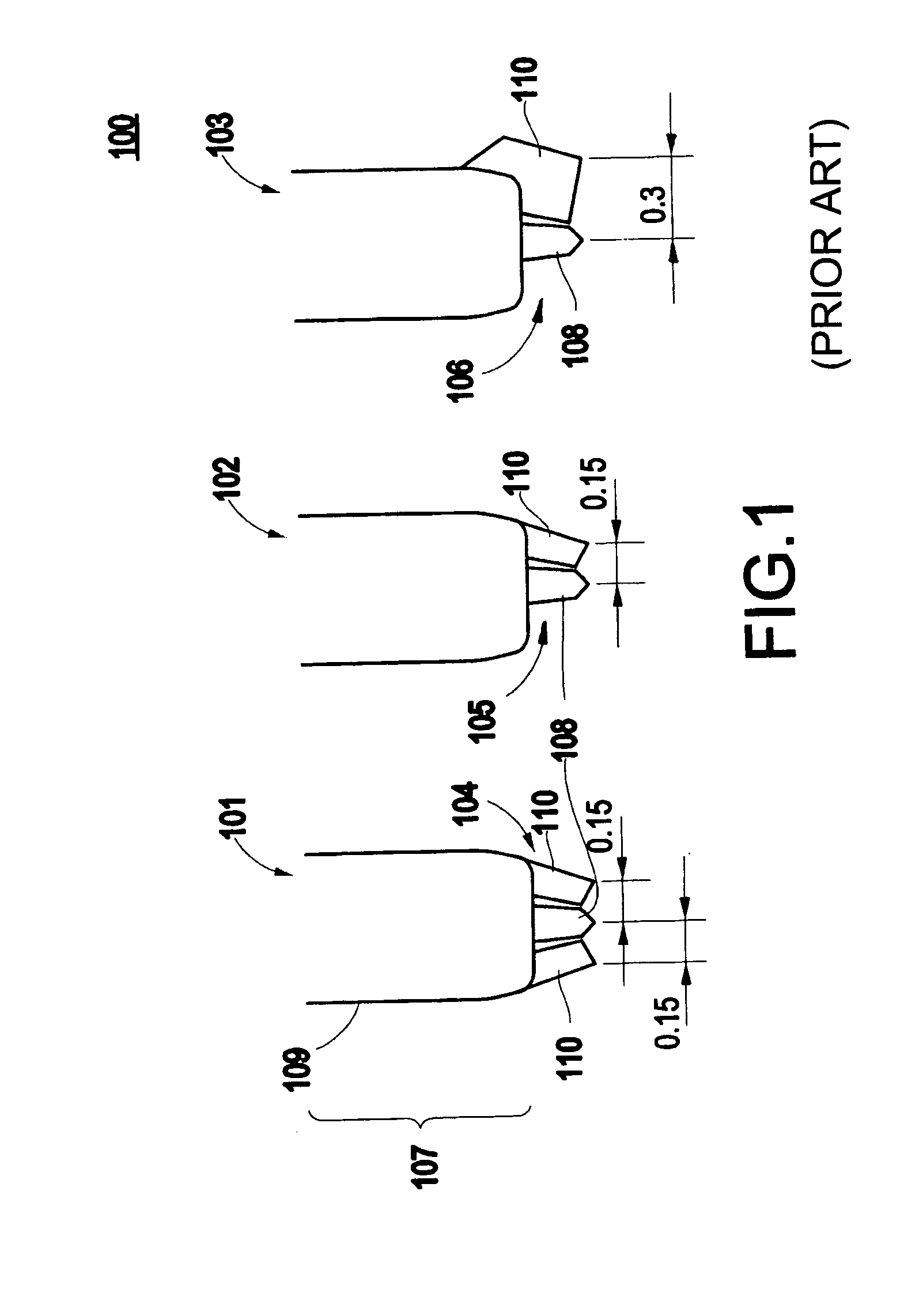
[0031]The present invention modifies the geometry of the conventional tips of these microwave probes (e.g., as shown in FIG. 1) to permit the user to set the pitch between the tip contact points over a wider range while maintaining minimal degradation in the high frequency performance. FIG. 2 shows key concepts of the present invention in greater detail, and FIGS. 3 and 4 show respective plane views looking from the perspectives indicated in FIG. 2.

[0032]The exemplary adjustable air coplanar waveguide (CPW) probe 200 of the present invention includes:[0033]a section of micro-coaxial 201, having outer wall 202 and center conductor 203;[0034]at least one peripheral probe element 204 (exemplarily, a probe element for ground) attached to the outer wall 202 such that the shape presents a taper that leaves a variable gap 205 between the outer ...


PUM

PropertyMeasurementUnit
electricalaaaaaaaaaa
conductiveaaaaaaaaaa
wavelengthsaaaaaaaaaa

Abstract

A coplanar waveguide (CPW) probe includes at least one center probe element, each having a respective center probe contact point and at least one peripheral probe element, each having a respective peripheral contact point. The pitch between the at least one center contact point and the at least one peripheral contact point is adjustable.

Description

BACKGROUND OF THE INVENTION[0001]1. Field of the Invention[0002]The present invention generally relates to test probes for characterizing microwave frequency circuits and packages. More specifically, a variable pitch air coplanar waveguide (CPW) structure allows the pitch of the CPW tips to be adjusted to accommodate a range of pad pitches with minimal degradation in the microwave performance of the probe launch.[0003]2. Description of the Related Art[0004]High performance (e.g. 40 GHz bandwidth) microwave probes are currently available for on-wafer testing of microwave frequency circuits. They are also being used increasingly for package level characterization as well.[0005]These probes are usually constructed of very small diameter micro-coaxial cable which is terminated on the device-under-test (DUT) end in an air coplanar waveguide (CPW) structure in a Ground-Signal-Ground (G-S-G) or similar configuration. A serious disadvantage of these probes is their high cost (in some cases,...

Claims


Application Information

Patent Timeline
Patent Type & Authority Patents(United States)
IPC IPC(8): G01R31/02H01P1/00G01R1/067
CPCG01R1/06772Y10T29/49002
Inventor KWARK, YOUNG HOON
Owner GLOBALFOUNDRIES INC
Why Eureka
Try Eureka