Digital skin lesion imaging system and method

a skin lesion and digital technology, applied in the field of computer imaging system and method, can solve the problems of small cancers that are often fatal, the physician observing the lesion usually does not have prior knowledge, and the difficulty of detecting early changes in the size of skin lesion, etc., and achieve the effect of convenient us

Inactive Publication Date: 2007-01-09
WESTERN RES
View PDF6 Cites 85 Cited by
  • Summary
  • Abstract
  • Description
  • Claims
  • Application Information

AI Technical Summary

Benefits of technology

[0012]Accordingly, it is an object of the invention to provide an inexpensive, easily used system / method for detecting new skin lesions and / or skin lesions which have grown significantly.

Problems solved by technology

Unfortunately, most people have difficulty detecting early changes in the size of a skin lesion because initial changes in size are slow and subtle.
Furthermore, a physician observing a lesion usually does not have prior “baseline” or reference information on the lesion from which to judge the amount or rate of its growth.
Because there is no generally effective treatment for metastatic melanoma, even small cancers often prove fatal if not detected early.
Various difficulties were encountered in providing a practical implementation of the basic technique described in that article using a microcomputer-based video imaging system for storing an image archive of historical reference images for each patient, registering and scaling current images with baseline images, and using an “alternating image comparison display” comparison of the image pairs in a manner that is readily acceptable by and useable by patients.
However, we learned that in a clinical setting the spatial resolution of the images acquired in this manner was poor.
But that was found to be impractical in a clinical setting because the procedure is very labor-intensive and time-consuming.

Method used


Image

  • Digital skin lesion imaging system and method
  • Digital skin lesion imaging system and method
  • Digital skin lesion imaging system and method

Examples


Embodiment Construction

[0026]In attempting to solve the above mentioned problems regarding clinical use of the system described in our above-mentioned U.S. Pat. No. 6,427,022, we found that we could make large-format images with improved, inexpensive digital cameras which are now available instead of using a film camera, although the problem of precise registration / alignment of baseline images and current images to be alternately displayed nevertheless remained unsolved.

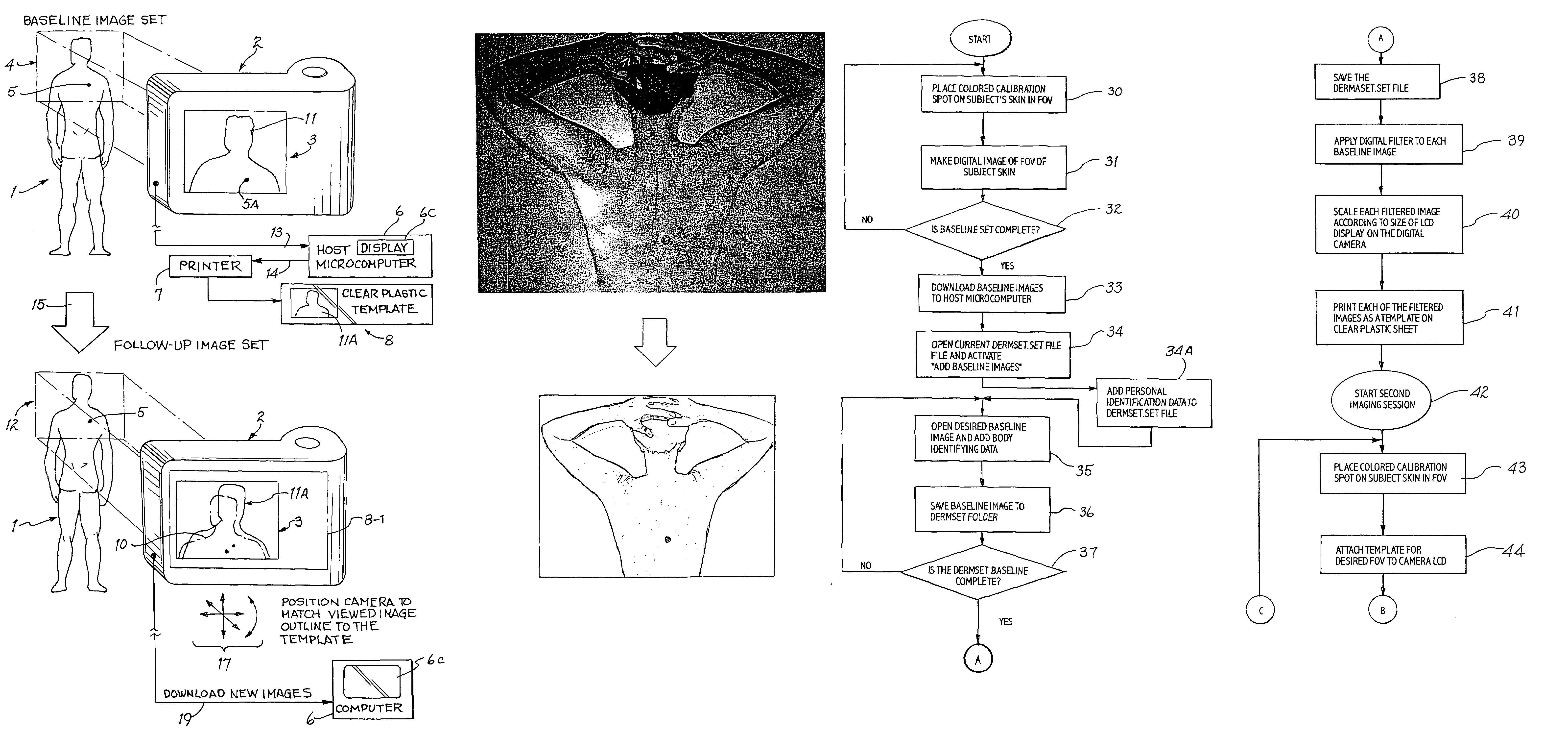
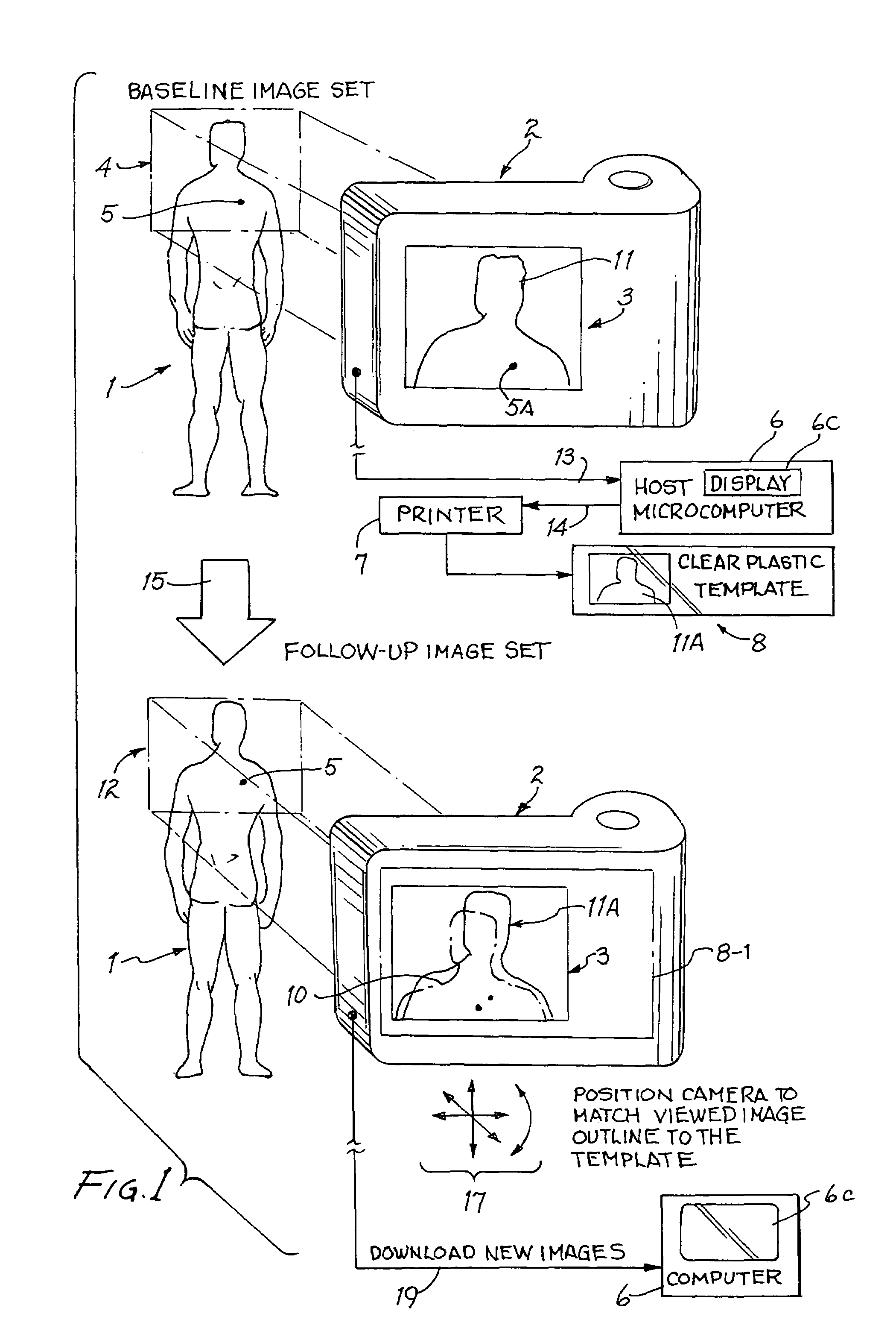
[0027]FIG. 1 shows how one of the skin areas of a subject 1 are photographed using an ordinary digital camera 2 having an LCD viewfinder display 3 in order to acquire one of a set of “baseline images” for subject 1. The field of view (FOV) of digital camera 2 is indicated by a rectangle 4 which encompasses the head and shoulders of subject 1. An adhesive-backed blue circular calibration disk 5 having a precisely known diameter may be attached to the skin of subject 1 within the field of view 4. (Alternatively, the calibration disk 5 can be...


PUM


Abstract

New or significantly changed skin lesions are detected by providing digital baseline image data of an area of a subject's skin by placing a calibration piece on the area and then positioning a digital camera to frame the area within a field of view of the camera and digitally photographing the area to produce a digital baseline image of the area. The digital baseline image is downloaded from the camera to a computer, which digitally filters the baseline image to produce a partially transparent baseline image scaled to fit over a viewfinder display of the camera. The filtered baseline image is printed on a transparent sheet to produce template. Substantially later, a calibration piece is placed on the area, and the template is placed over the viewfinder display of the camera. The camera is positioned to frame that area within the field of view so as to align a live image of the area with the baseline image on the template. The area is photographed to produce a digital current image thereof. The current image is downloaded to the computer, which is operated to alternately display the aligned current image data and the baseline image data to allow visual identification of lesions which changed enough in the “alternating image comparison display” to identify a new or significantly growing lesion.

Description

CROSS REFERENCE TO RELATED APPLICATION[0001]This application claims the benefit of prior filed co-pending U.S. provisional application Ser. No. 60 / 490,827 filed Jul. 29, 2003 entitled “Digital Skin Lesion Imaging System and Method” by Eric R. Craine and Brian L. Craine.BACKGROUND OF THE INVENTION[0002]The invention relates to a computer imaging system and method for detecting new skin lesions and significant changes in existing skin lesions.[0003]It is well known that rapid changes in the size of a mole or skin lesion may indicate the onset of precancerous or cancerous tissue growth and that early detection of such changes usually results in a much better prognosis for the patient, especially if the lesion is a melanoma. In the case of a melanoma, a delay of a month or two in detection may make the difference between successful treatment or death of the patient. Unfortunately, most people have difficulty detecting early changes in the size of a skin lesion because initial changes in...

Claims


Application Information

Patent Timeline
Patent Type & Authority Patents(United States)
IPC IPC(8): G06K9/00
CPCG06T7/0012Y10S128/922G06T2207/30024G03B17/56
Inventor CRAINE, ERIC R.CRAINE, BRIAN L.
Owner WESTERN RES
Why Eureka
Try Eureka