
Oxide high-temperature superconducting wire and method of producing the same

a superconducting wire and high-temperature technology, applied in the direction of superconducting magnets/coils, magnetic bodies, natural mineral layered products, etc., can solve the problems of insufficient reduction of ac loss, difficult to make such barriers with a uniform density and thickness in limited spaces, and difficult to increase the perpendicular resistance between, so as to reduce ac loss

Inactive Publication Date: 2007-01-09
SUMITOMO ELECTRIC IND LTD
View PDF43 Cites 5 Cited by
  • Summary
  • Abstract
  • Description
  • Claims
  • Application Information

AI Technical Summary

Benefits of technology

The present invention provides an improved oxide superconducting wire with reduced AC loss and a method of producing it. The wire has a structure with a ceramic layer that acts as a high-resistant barrier or an insulator, making it possible to achieve a high perpendicular resistance. This results in a reduction of AC loss and a higher critical current density. The ceramic layer is permeable to air, allowing for the release of oxygen and other gases generated during the production process. The wire also has a metal sheath that facilitates processing of the oxide superconductors and can be made from silver, copper, manganese, magnesium, antimony, iron, chromium, or nickel. The ceramic layer can be formed by extrusion or other methods and can contain alkali earth metals, copper, manganese, magnesium, antimony, iron, chromium, or nickel. The wire can also have a spiral structure to further reduce AC loss. Overall, the invention provides an improved oxide superconducting wire with reduced AC loss and a method of producing it.

Problems solved by technology

A multifilament oxide superconducting wire incorporating silver sheaths is disadvantageous in that AC loss cannot be reduced sufficiently because silver as a sheath has low resistance.
However, it is difficult to make such barriers with a uniform density and thickness in limited spaces between the filaments.
This subsequently makes it difficult to increase perpendicular resistance between the filaments to such a desirable level as to reduce AC loss.
Furthermore, making the barrier layers thicker to realize sufficient resistance may, in turn, lead to decreasing the ratio of the superconducting filaments contained in the total oxide superconducting wire and subsequently making current density lower.
Upon coating the slurry, the barrier layers tended to have such a low density that they were prone to irregular deformation and were not formed uniformly.
This prevents the crystallic axis of the oxide superconductors from being oriented uniformly, lowers critical current, and consequently makes it difficult to apply the superconducting wire to a practical use.
Further the conventional oxide superconductors were not capable of effectively releasing oxygen and other gases outside that were generated during a reaction process, as the superconductors were coated with silver sheaths.
It is impossible, however, to completely bond the plural crystal grains of the oxide superconductor together, once they are formed as a result of the reaction, even if such subsequent second-stage plastic deformation and heat treatment are conducted.
In heat treatment, excessively increased temperature for bonding the crystal grains may cause the once-formed oxide superconductor to melt and break up into different phases including a non-superconducting phase.
A cross-section reduction ratio of plastic deformation and compressive stress applied to the oxide superconductor, if increased excessively, may create cracks of the crystal grains in the oxide superconductors and increase a portion where the bonding between the grains is not sufficient.
Conventional oxide superconducting wires employed metal pipes, especially expensive silver pipes, considering their effective affinity with the oxide superconductors.
For the aforementioned reasons, overall production cost has soared and become a major impediment to wider applications of an oxide superconducting wire as an industrial product.

Method used


Image

  • Oxide high-temperature superconducting wire and method of producing the same
  • Oxide high-temperature superconducting wire and method of producing the same
  • Oxide high-temperature superconducting wire and method of producing the same

Examples


embodiment 1

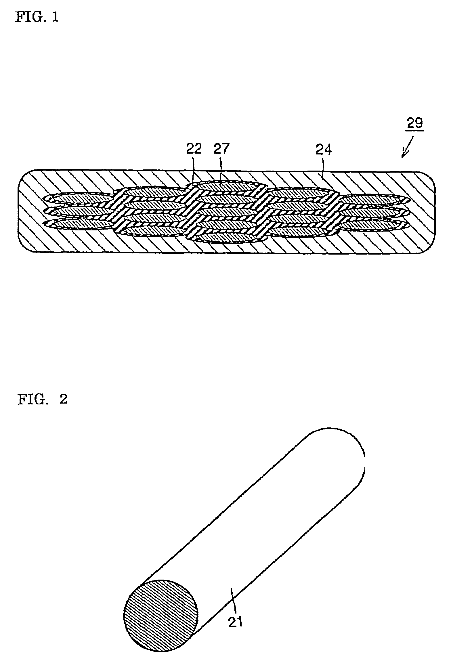
[0112]FIG. 1 shows a cross section of an oxide superconductor wire produced in accordance with the first embodiment of the present invention. The oxide superconducting wire 29 comprises oxide superconducting filaments 27, a ceramic layer 22, and a silver sheath 24 as a metal pipe. Each of the superconducting filaments 27 is in contact and coated with the ceramic layer 22. The ceramic layer 22 containing a metal oxide becomes non-conductive at an operating temperature of the filaments 27. The ceramic layer 22 is in contact and coated with the silver sheath 24. The oxide superconducting wire 29, which is formed into a tape, extends from an end whose sectional view is illustrated in FIG. 1 toward the other end not illustrated herein. The filaments 27, the ceramic layer 22, and the silver sheath 24 have flat structures elongated laterally. The filaments 27 consist of, for example, (Bi, Pb)2 Sr2 Ca2 Cu3Ox. The oxide superconducting wire 29 contains a plurality of the filaments 27. The fi...

embodiment 2

[0119]FIG. 8 is a cross section of an oxide superconducting wire produced in accordance with the second embodiment of the present invention. The oxide superconducting wire 39 comprises oxide superconducting filaments 37, a ceramic layer 31, and a silver sheath 34 as a metal pipe. The filaments 37 are each in contact and coated with the ceramic layer 31, which become non-conductive when the filaments 37 are cooled to an operating temperature. The ceramic layer 31 is in contact and coated with the silver sheath 34. The oxide superconducting wire 39 is a tape shape extending from the end whose cross section is shown in FIG. 8 toward the other direction not illustrated herein. The filaments 37, the ceramic layer 31 and the silver sheath 34 are formed into tape-shaped structures having a flat cross-section elongated laterally. The filaments 37 consist of, for example, (Bi, Pb)2 Sr2 Ca2 Cu3Ox. The oxide superconducting wire 39 includes a plurality of the filaments 37 which are each surrou...

embodiment 3

[0126]FIG. 15 is a cross section of an oxide superconducting wire produced in accordance with the third embodiment of the present invention. The oxide superconducting wire 49 comprises oxide superconducting filaments 47, a ceramic layer 48, and a silver sheath 44 as a metal pipe. The filaments 47 are each in contact and coated with the ceramic layer 48, which become non-conductive when the filaments 47 are cooled to an operating temperature. The ceramic layer 48 is in contact and coated with the silver sheath 44. The oxide superconducting wire 49 is a tape shape extending from the end whose cross section is shown in FIG. 15 toward the other direction not illustrated herein. The filaments 47, the ceramic layer 48 and the silver sheath 44 are formed into tape-shaped structures having a flat cross-section elongated laterally. The filaments 47 consist of, for example, (Bi, Pb)2 Sr2 Ca2 Cu3 Ox. The oxide superconducting wire 49 includes a plurality of the filaments 47 which are each surr...


PUM

PropertyMeasurementUnit
thicknessaaaaaaaaaa
thicknessaaaaaaaaaa
frequencyaaaaaaaaaa

Abstract

This invention relates to an oxide superconducting wire comprising oxide superconducting filaments, a high-density ceramic layer uniformly surrounding each of the filaments, and a silver sheath that directly covers the ceramic layer. The ceramic layer becomes non-superconducting when the filaments are cooled to an operating temperature of oxide superconductors. The oxide superconductors can be isolated by the ceramic that acts as a highly resistive material or an insulator. A high normal resistance is achieved, and thereby AC loss is reduced remarkably.

Description

CROSS-REFERENCE TO RELATED PATENT APPLICATIONS[0001]This application is a division of application Ser. No. 09 / 938,829, filed Aug. 27, 2001, now abandoned, and based on Japanese Patent Application No. 2000-258753, filed Aug. 29, 2000, by Naoki AYAI This application claims only subject matter disclosed in the parent application and therefore presents no new matter.BACKGROUND OF THE INVENTION[0002]1. Field of the Invention[0003]The present invention relates to an oxide superconducting wire and method of producing the same. More particularly, the invention relates to oxide superconducting wires and methods of producing the same that are intended for applications in such fields as electric power supply, transportation, high-energy physics, and medical instruments.[0004]2. Description of the Background Art[0005]In recent years, it has been reported that sintered oxide materials exhibit superconducting property at high critical temperatures, and practical applications of superconduction te...

Claims


Application Information

Patent Timeline
Patent Type & Authority Patents(United States)
IPC IPC(8): H01B12/00H01F6/00H01L39/00H01L39/24H01F6/06H01B12/10H01B13/00H10N60/00H10N60/01H10N60/20
CPCH01L39/248H01L39/143H10N60/203H10N60/0801
Inventor AYAI, NAOKI
Owner SUMITOMO ELECTRIC IND LTD
Learn More