
Non-contact power feeding coil and non-contact power feeding system

a power feeding coil and non-contact technology, applied in the direction of transformer/inductance magnetic cores, charging stations, transportation and packaging, etc., can solve the problems of power feeding efficiency decline and increase in loss, and achieve favorable power feeding efficiency and suppress the effect of ac loss caused by proximity

Active Publication Date: 2020-06-02
FUJI CORP
View PDF29 Cites 0 Cited by
  • Summary
  • Abstract
  • Description
  • Claims
  • Application Information

AI Technical Summary

Benefits of technology

[0014]In addition, in the technical example of PTL 3, even if it is possible to prevent electromagnetic leakage to outside the magnetic body, leakage flux enters the shielding case on the inner side of the magnetic body. Accordingly, eddy current loss is generated in the shielding case and there is an increase in loss. In addition, the litz wire disclosed in PTL 4 is expensive compared to a wire composed of a single conductor, but it is possible to significantly reduce AC loss caused by a skin effect. However, there is a concern that shape loss will occur in the cross-sectional shape of the litz wire during winding work, and that the effect of reducing AC loss will be lost.
[0015]In the above-mentioned manner, when loss of a power feeding coil and a power receiving coil is increased, naturally, the power feeding efficiency of the non-contact power feeding system decreases.
[0020]In the non-contact power feeding system of the present disclosure, favorable power feeding efficiency can be obtained.

Problems solved by technology

However, as a result of the frequency being high, loss increases due to AC loss and leakage flux of a coil, and therefore, there is a tendency for power feeding efficiency to decrease.
In addition, since an electric current flows into and heat is generated in peripheral metal objects to which leakage flux reaches, an increase in loss is caused.

Method used


Image

  • Non-contact power feeding coil and non-contact power feeding system
  • Non-contact power feeding coil and non-contact power feeding system
  • Non-contact power feeding coil and non-contact power feeding system

Examples


Embodiment Construction

1. Entire Configuration of Non-Contact Power Feeding System 1 of Embodiment

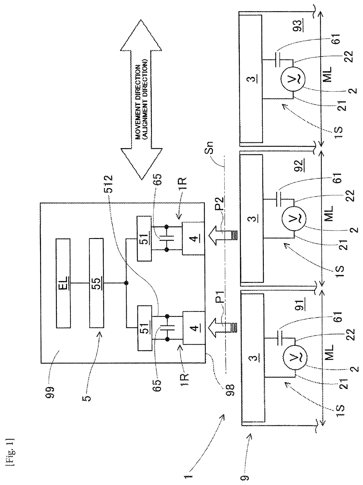
[0031]A non-contact power feeding system 1 of an embodiment of the present disclosure will be described below with reference to FIG. 1. FIG. 1 is a view that schematically describes an entire configuration of the non-contact power feeding system 1 of the embodiment. The non-contact power feeding system 1 of the embodiment can be applied to a board production line 9. As illustrated in the drawings, the board production line 9 is configured by three first to third board production machines 91 to 93 being linearly arranged. The left-right direction in FIG. 1 is a linear arrangement direction of the first to third board production machines 91 to 93, and is also a movement direction of a moving body 99, which will be mentioned later.

[0032]Each board production machine 91 to 93 is modularized, and width dimensions ML in the linear arrangement direction thereof are equivalent. The first to third board production mac...


PUM

PropertyMeasurementUnit
specific frequencyaaaaaaaaaa
coil resistanceaaaaaaaaaa
DC resistanceaaaaaaaaaa

Abstract

A power feeding coil that configures a non-contact power feeding system is provided. The power feeding coil is provided with a coil through which an AC current of a specific frequency flows, and a core that forms a section of a circulating magnetic path, which is interlinked with the coil. In the coil, a wire having an insulating covering is wound around a conductor, and a covering thickness of the insulating covering is set so that the influence of a proximity effect that occurs at the specific frequency between adjacent portions of the wire is a predetermined amount or less. According to this configuration, it is possible to freely adjust a separation distance between portions of the conductor by altering the covering thickness; and the occurrence of AC loss caused by a proximity effect may be appropriately suppressed.

Description

TECHNICAL FIELD[0001]The present disclosure relates to a non-contact power feeding coil provided with a coil and a core, and to a non-contact power feeding system configured using the non-contact power feeding system.BACKGROUND ART[0002]A solder printing machine, an electronic component mounting machine, a ref low machine, aboard inspection machine, and the like, are examples of board production machines that produce boards on which multiple components are mounted. Generally, a board production line is configured by linking such equipment. Furthermore, there are many cases in which a board production line is configured by linearly arranging modularized board production machines of the same size. As a result of the use of modularized board production machines, setup changing work during rearrangement of a line and during expansion for increasing the size of a line is facilitated, and a flexible board production line is realized.[0003]In recent years, the promotion of labor-saving eff...

Claims


Application Information

Patent Timeline
Patent Type & Authority Patents(United States)
IPC IPC(8): H01F27/28H02J50/10H05K13/00H02J50/70H01F27/24H01F27/255B60L53/12B60L53/39H01F38/14H01F27/32H02J50/40
CPCH01F38/14H02J50/70H01F27/28B60L53/12H01F27/24H05K13/00H01F27/2871H01F27/2823H02J50/10B60L53/39H01F27/32H02J50/40H01F27/255Y02T10/70Y02T10/7072Y02T90/14Y02T90/12
Inventor OKI, MASAYUKITAKIKAWA, SHINJINOMURA, TAKESHIJINDO, TAKAHIRO
Owner FUJI CORP
Learn More