Flow control valve and flow control device

a flow control device and flow control technology, applied in the direction of valve housings, fluid pressure control, instruments, etc., can solve the problems of low flow adjustment accuracy, difficulty in fine adjustment of the separation amount of the upper diaphragm, and the seat of the valve to hinder the flow adjustment with high accuracy, etc., to achieve the effect of simple structur

Active Publication Date: 2007-01-16
TOFLO CORP
View PDF10 Cites 16 Cited by
  • Summary
  • Abstract
  • Description
  • Claims
  • Application Information

AI Technical Summary

Benefits of technology

[0011]In the flow control valve according to the invention, the pressure of the air supplied into the air chamber acts on the two diaphragms having the different pressurized areas. At this time, the difference between the areas of the pressurized surfaces of the diaphragms cause a difference between forces applied to the diaphragms. The differential force, that is, the force obtained by subtracting a force applied to the diaphragm having a smaller pressurized area from a force applied to the diaphragm having a larger pressurized area, acts on a connection structure constituted by the upper and lower diaphragms and the connecting shaft to deform and displace the connection structure. The deforming and displacing operation is such that the diaphragm having the larger pressurized area is deformed and displaced so as to protrude toward the outside of the air chamber, the deformation of the diaphragm causes the connecting shaft to slide, and the diaphragm having the smaller pressurized area is deformed and displaced toward the inside of the air chamber via the connecting shaft. Simultaneously with the deforming and displacing operation, the valve body slides in conjunction with the sliding operation of the connecting shaft to increase or decrease the flow rate of the fluid flowing through the internal channel.
[0036](1) Flow control of a fluid may be performed with high accuracy.

Problems solved by technology

The diaphragm valve in Japanese Patent Laid-Open No. 2003-185053, however, has the structure in which the pressure of the air from the air supply piping 54 is applied to the piston 53 to deform the upper diaphragm 50, and thus an amount of change in the pressure when the pressure of the air is changed is directly reflected in an amount of deformation of the upper diaphragm 50 and an amount of separation from the valve seat 55, thereby making it difficult to finely adjust the amount of separation of the upper diaphragm 50 from the valve seat to hinder a flow adjustment with high accuracy.
Because the diaphragm valve itself has low flow adjustment accuracy, flow control of a fluid with high accuracy cannot be expected in a flow control device using such a diaphragm valve.
Thus, in the pilot regulator, an amount of change in the operating pressure for vertically displacing the diaphragm is directly reflected in an amount of displacement of the diaphragm and an amount of vertical movement of the valve body, thereby hindering a flow adjustment with high accuracy like the flow control valve in Japanese Patent Laid-Open No. 2003-185053.
Because the pilot regulator itself has low flow adjustment accuracy, flow control of a fluid with high accuracy cannot be expected in a flow control device using such a pilot regulator.

Method used


Image

  • Flow control valve and flow control device
  • Flow control valve and flow control device
  • Flow control valve and flow control device

Examples


Embodiment Construction

[0044]Now, a preferred embodiment of the invention will be described in detail with reference to the accompanying drawings.

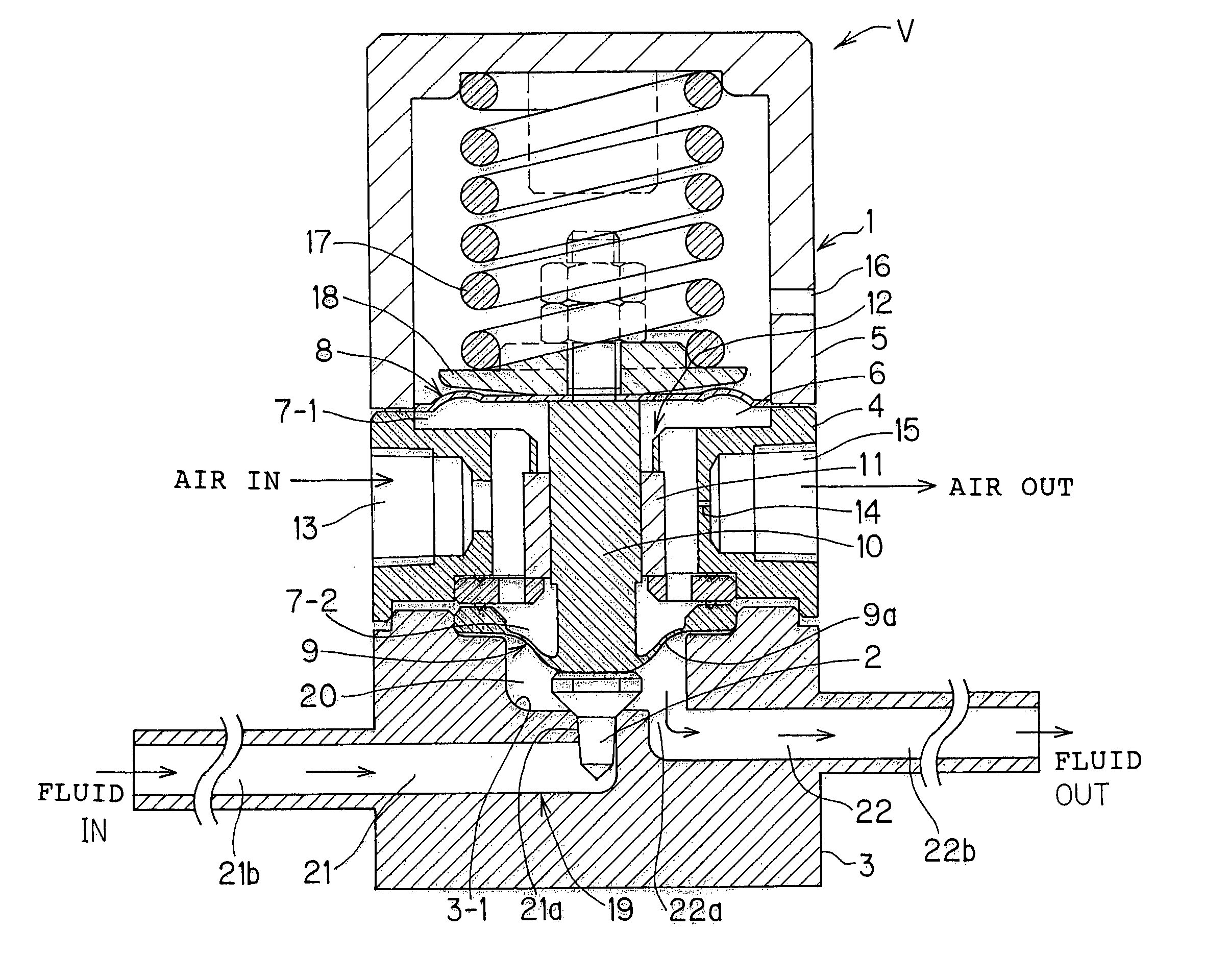
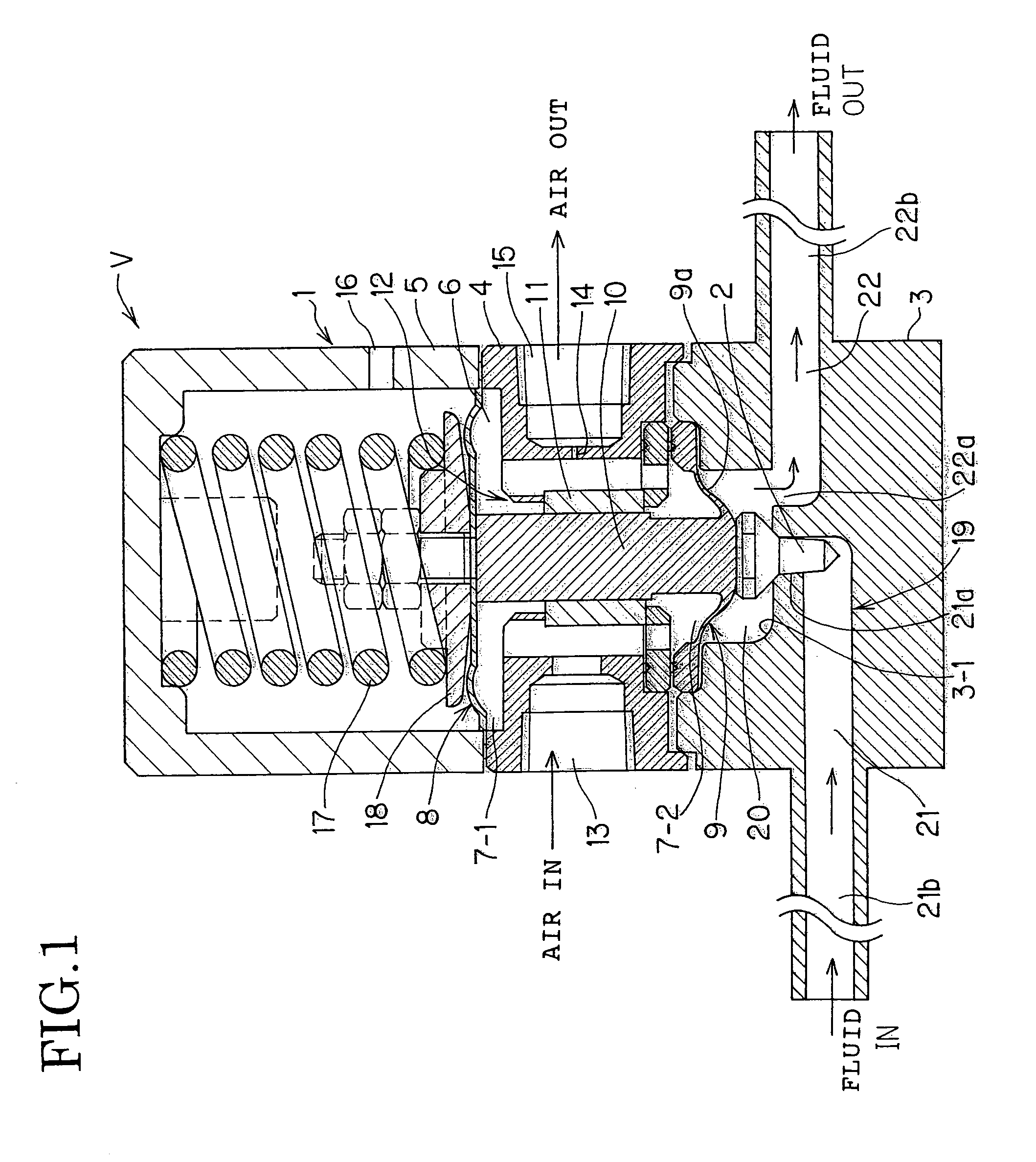
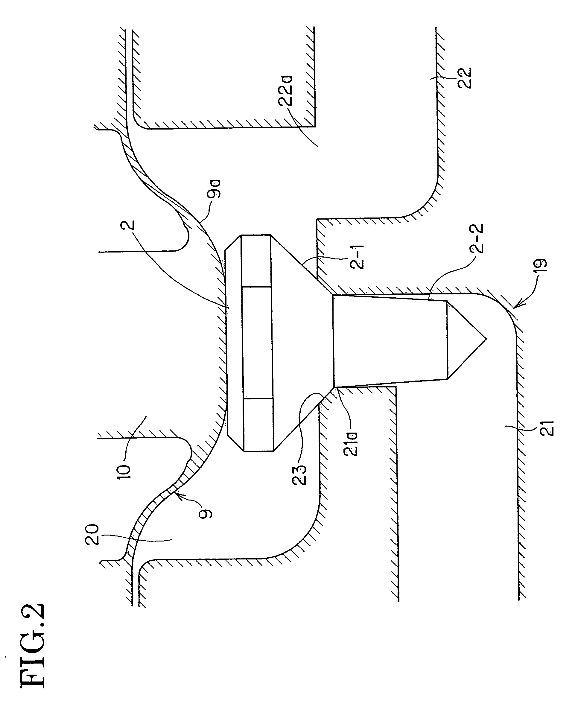
[0045]A flow control valve V in FIG. 1 includes a valve housing 1 that houses valve components such as a valve body 2. The valve housing 1 according to the embodiment includes a valve base 3 placed in a lower portion, a valve cap 5 placed in an upper portion, and a cylindrical middle housing 4 placed between the valve base 3 and the valve cap 5.

[0046]A cylindrical inner space of the middle housing 4 is provided as an air chamber 6. The air chamber 6 has two vertically opposite openings 7-1 and 7-2. A first diaphragm 8 is mounted to the upper opening 7-1 of the air chamber 6, a second diaphragm 9 is mounted to the lower opening 7-2 of the air chamber 6, and the two vertical diaphragms 8 and 9 close the upper opening 7-1 and the lower opening 7-2, respectively, of the air chamber 6.

[0047]Herein, the first diaphragm 8 that closes the upper opening 7-1 of the air ch...


PUM


Abstract

There are provided a flow control valve and a flow control device suitable for allowing flow control of a fluid with high accuracy. Diaphragms 8 and 9 are mounted to upper and lower openings, respectively, of an air chamber 6. The upper diaphragm 8 and the lower diaphragm 9 are connected by a connecting shaft 10 and have pressurized surfaces with different areas that receive pressure of the air chamber 6. This causes a difference between forces applied to the two diaphragms 8 and 9, and the difference causes the connecting shaft 10 and a valve body 2 mounted to an outer surface of the lower diaphragm 9 to slide and be separated from a valve seat 23.

Description

BACKGROUND OF THE INVENTION[0001]1. Field of the Invention[0002]The present invention relates to a flow control device and a flow control valve included in the flow control device used for a variety of devices that suitably control a flow rate of a fluid to supply the fluid, such as a flow control unit or the like in a semiconductor manufacturing apparatus.[0003]2. Description of the Related Art[0004]A known flow control valve is a diaphragm valve disclosed in Japanese Patent Laid-Open No. 2003-185053. The diaphragm valve in Japanese Patent Laid-Open No. 2003-185053 has a structure in which two upper and lower diaphragms 50 and 51 are connected by a link rod 52, and a piston 53 is connected to the upper diaphragm 50. When the piston 53 is moved upward by pressure of air from air supply piping 54, the movement of the piston 53 causes the upper diaphragm 50 to be deformed and separated from a valve seat 55 to open a channel 56 through which a fluid flows.[0005]The diaphragm valve in J...

Claims


Application Information

Patent Timeline
Patent Type & Authority Patents(United States)
IPC IPC(8): G05D7/06F16K31/126F16K31/12G05D16/18
CPCG05D16/185F16K31/1268Y10T137/7759Y10T137/7761F16K31/1262F16K1/34F16K27/02
Inventor IGAWA, AKINORITAKEMOTO, SHOJI
Owner TOFLO CORP
Why Eureka
Try Eureka