Drill head

a drill head and drilling head technology, applied in the direction of drilling pipes, drilling holes/well accessories, cutting machines, etc., can solve the problems of increasing the drilling advance with an increased press-on pressure, and achieve the effect of increasing the drilling advance and increasing the press-on pressur

Inactive Publication Date: 2007-01-16
HILTI AG
View PDF12 Cites 1 Cited by
  • Summary
  • Abstract
  • Description
  • Claims
  • Application Information

AI Technical Summary

Benefits of technology

[0009]This and other objects of the present invention, which will become apparent hereinafter, are achieved by providing at least one suction opening that has a crushing profile. The crushing profile of the at least one opening prevents a direct penetration of coarse drilling into the drill pipe. Fine drillings are directly aspirated through the suction opening(s), whereas the coarse drilling are further comminuted or crushed and only then are aspirated. Further, the crushing profile reduces the surface of the cutting side of the drill head which leads to an increased drilling advance with an increased press-on pressure. With conventional drill head the press-on pressure is in a range from 10 to 25 kN. The inventive drill head with a crushing profile at the suction opening can also be used in a wet drilling process.
[0012]Advantageously, radial distance of the tooth crowns of the toothing from the center of the drill head decreases. Such formation of the crushing profile insures comminuting of coarse drillings and prevents to a most possible extent clogging of the drill pipe in the underground even with hard drillings. Advantageously, the radial distances of the tooth crowns of the crushing profile from the drill head center decreases continuously.
[0013]Advantageously, the depressions between the tooth crowns have a cross-section of a circular segment. This insures a certain swirling of coarse drillings, providing for further crushing, which facilitate comminuting of coarse drilling.
[0014]Advantageously, the tooth roots of the toothing lie essentially on a circle having its center in the center of the bore head. The radius of this circle is advantageously so selected that remaining opening on the cutting side for removal of drillings have a cross-section which does not permit passing therethrough and into the drill pipe of coarse drillings. In addition, the arrangement of tooth roots on a circle having its center in the center of the drill head insures an adequate support of the bit which is either formed on or inserted into the cutting side of the drill head, which insures that the drill head can absorb loads acting on the cutting bit. The arrangement of the tooth roots on a circle having its center in the center of the drill head in combination with the reduction of radial distances of the tooth crown provides for continuous reduction of the receiving regions between the tooth crowns of the toothing along the toothing. This prevents, on one hand, retention of coarse drillings in the depressions of the toothing and, on the other hand, reduces a danger of jamming of the drill head in a constructional component.

Problems solved by technology

Further, the crushing profile reduces the surface of the cutting side of the drill head which leads to an increased drilling advance with an increased press-on pressure.

Method used


Image

  • Drill head
  • Drill head

Examples


Embodiment Construction

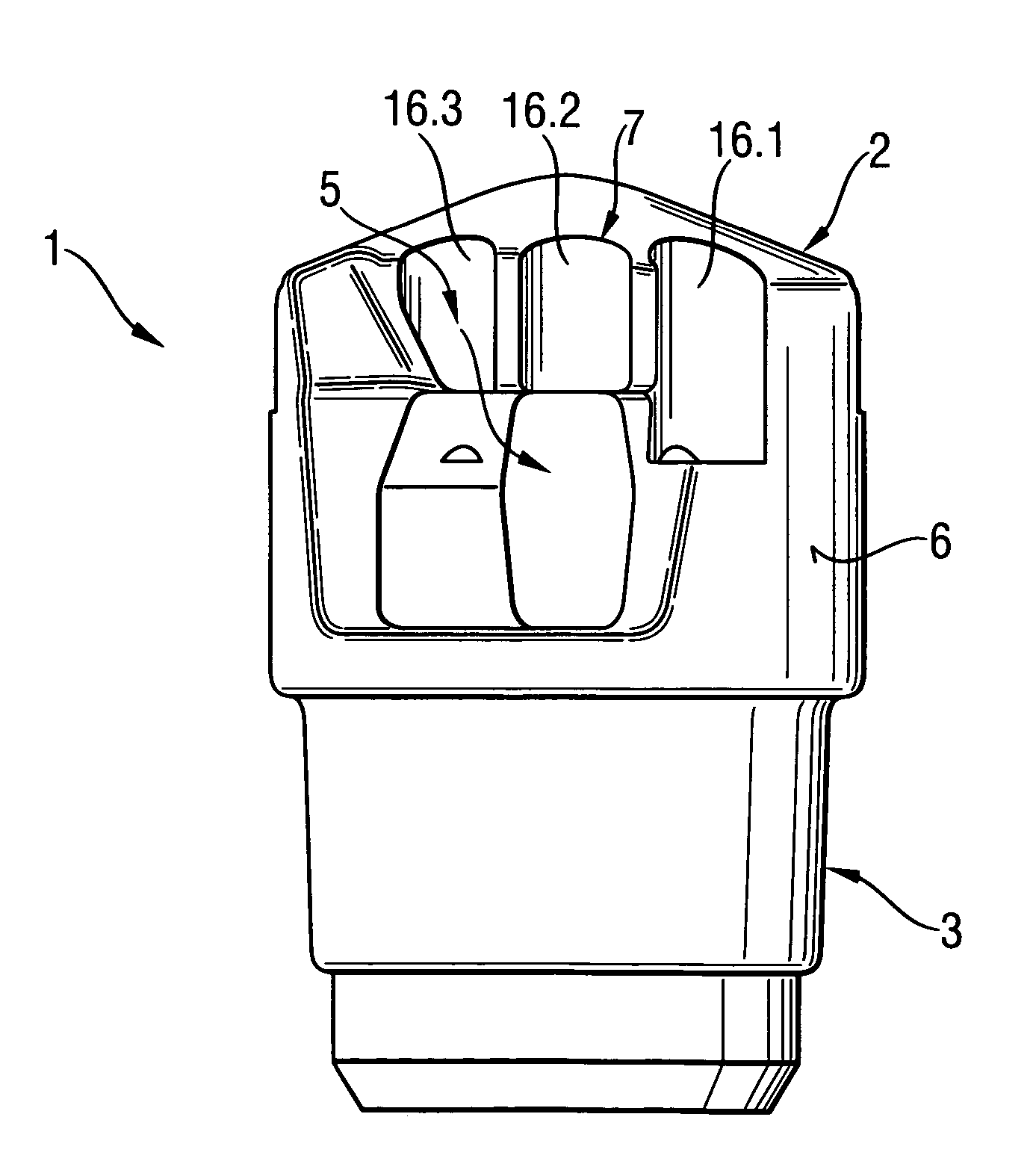
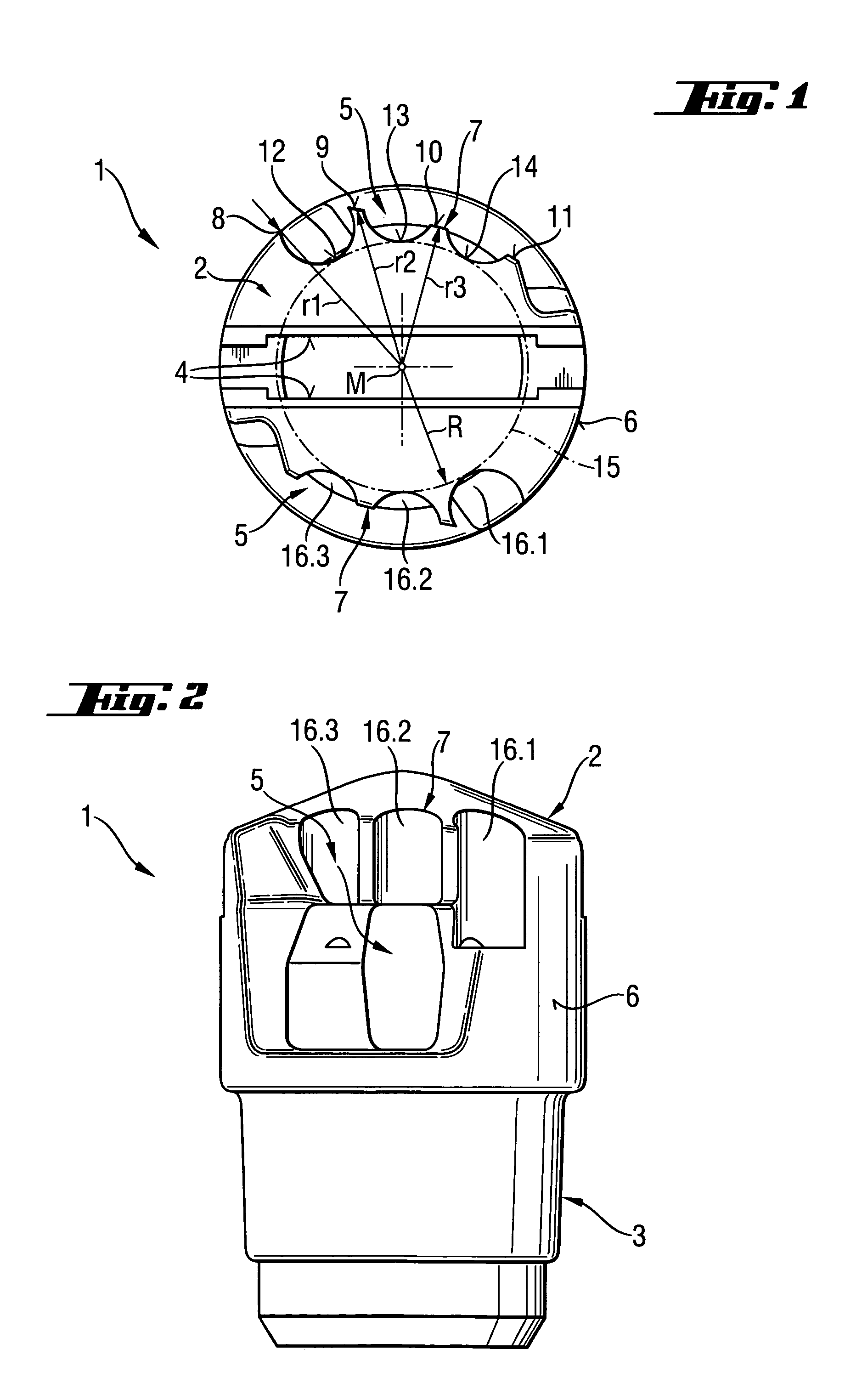
[0020]A drill head 1 according to the present invention, which is shown in FIGS. 1–2, has a cutting side 2 and is provided at its end opposite, in the longitudinal direction of the drill head 1, the cutting side 2 with a shank section 3. Before a start of a drilling process, the drill head 1 is inserted with its shank section 3 in a tubular drill pipe. The cutting side 2 of the drill head 1 has a recess 4 for receiving an insertable cutting bit formed, e.g., of a hard material. At the cutting side 2, there are further provided two, diametrically opposite suction openings 5 which have, on an outer radial side 6 of the drill head 1, a toothing 7 forming a crushing profile.

[0021]The toothing 7 is uniformly formed and has a plurality of tooth crowns 8, 9, 10 and 11 and a plurality of tooth roots 12, 13 and 14. The radial distances r1, r2 and r3 of tooth crowns 8, 9 and 11 from a center M continuously decrease. The roots 12, 13 and 14 lie on a circle 15 having a radius R. Depressions 16....


PUM


Abstract

A drill head for use in drilling bores in mines and tunnels has a bit and at least one suction opening (5) for removing drillings and having a crushing profile.

Description

BACKGROUND OF THE INVENTION[0001]1. Field of the Invention[0002]The present invention relates to a drill head for drills, in particular for drills usable in mine and tunnel constructions, and having a bit, which can be inserted into the drill head or formed thereon, and at least one suction opening for removing drillings.[0003]2. Description of the Prior Art[0004]Drill heads of the type described above are used in dry drilling processes and are usually put on tubular drill pipes. The drill heads have usually a bit formed at the cutting side, or an insertable hard material bit receivable in a recess provided on the cutting side. On the cutting side, there is provided at least one suction opening that enables aspiration of drillings through the drill pipe.[0005]A drill head of the type discussed above is disclosed, e.g., in U.S. Pat. No. 4,711,312 and has a hard material bit inserted in a recess formed in the cutting side and projecting therefrom beyond the cutting side of the drill h...

Claims


Application Information

Patent Timeline
Patent Type & Authority Patents(United States)
IPC IPC(8): E21B10/36E21B10/60
CPCE21B10/60
Inventor GIENAU, ROLANDLUDWIG, WOLFGANGLEIBHARD, ERICH
Owner HILTI AG
Why Eureka
Try Eureka