Rotatable assembly for machines

a technology of rotating parts and machines, applied in the direction of solid separation, sorting, grading, etc., can solve the problems of inoperable operation, torsional load and bending load in the same plane of the shaft, and the inability of processing tools to break down, so as to reduce the diameter of the shaft, reduce the effect of detrimental shock and concentrated load

Inactive Publication Date: 2007-01-16
SMORACY
View PDF98 Cites 16 Cited by
  • Summary
  • Abstract
  • Description
  • Claims
  • Application Information

AI Technical Summary

Benefits of technology

[0010]One advantage of the present invention is that a rotatable assembly is provided for a machine having a bearing that allows twisting of the shaft so that the shaft experiences less detrimental shock and concentrated loading. Another advantage of the present invention is that the rotatable assembly allows a diameter of a shaft to be reduced by keeping stress in a manageable range for the same deflection, thereby saving material and manufacturing costs. Yet another advantage of the present invention is that the rotatable assembly prevents concentrated stress from being in the same plane for torsion or bending. Still another advantage of the present invention is that the rotatable assembly has other components attached to the shaft, such as drive belts and the like, which last longer due to the reduced stress. A further advantage of the present invention is that the rotatable assembly increases the operating life of the shaft, lessening the expense and time of repairs to and replacement of the rotatable assembly.

Problems solved by technology

When non-grindable materials, such as rocks and other hard debris, enter the waste processing machine, the processing tools are unable to break them down.
More specifically, loading of the first and second sets of braces results in a torsional load and bending load in the same plane on the shaft.
These combined loads can cause deformation or breakage of the drive end of the shaft, which renders it inoperable.
Users can replace the shaft, but replacement typically costs a significant amount of money and machine downtime.
However, the larger diameter shafts cost more to make, which is undesired.
Moreover, increasing the diameter of the shaft does not ensure other components in the rotor assembly will withstand the high stresses caused by the non-grindables.
When the processing tools impact the non-grindables, the resultant shock load may cause the belt to break, costing the user significant time and money for repair.

Method used


Image

  • Rotatable assembly for machines
  • Rotatable assembly for machines
  • Rotatable assembly for machines

Examples


Embodiment Construction

)

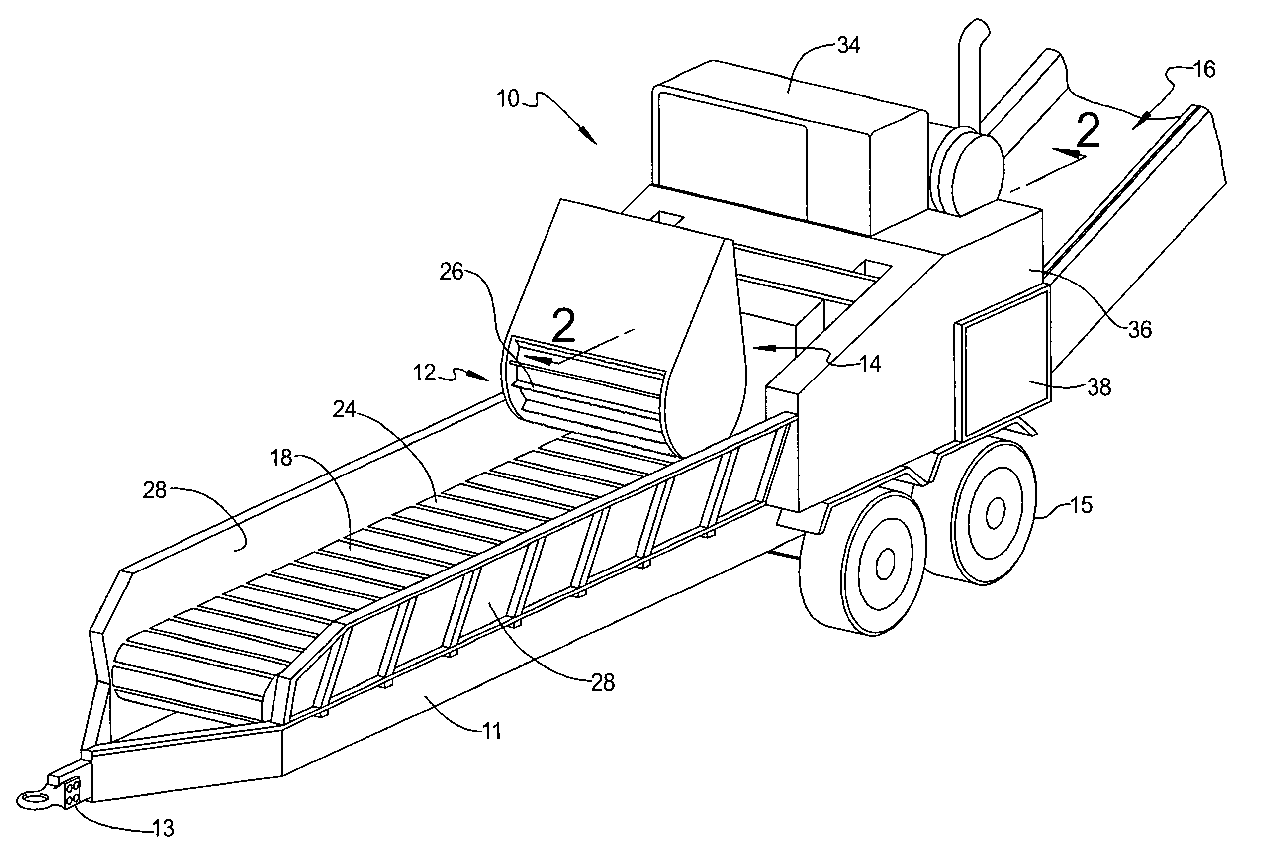
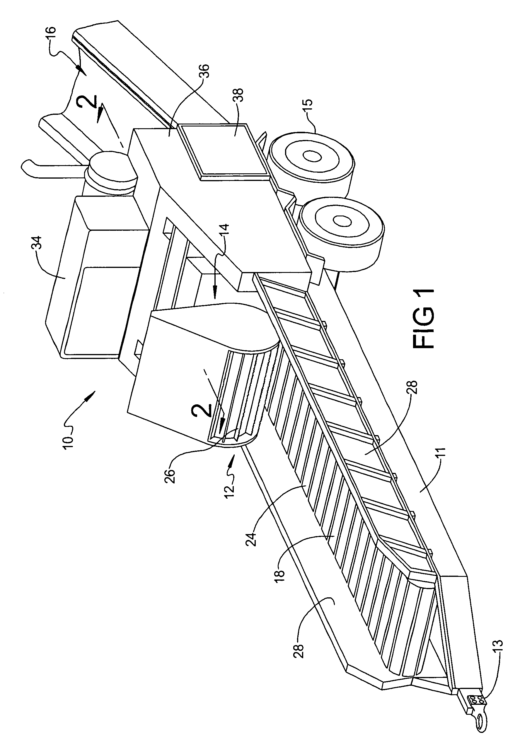
[0021]Referring now to the drawings and in particular to FIG. 1, one embodiment of a machine such as a waste processing machine 10 is shown. The waste processing machine 10 includes an infeed system 12, a waste reducing system 14, and a discharge system 16. Waste material enters the waste processing machine 10 through the infeed system 12 where it is directed to the waste reducing system 14. The waste reducing system 14 reduces the waste material and directs it to the discharge system 16 where the reduced waste material is expelled from the waste processing machine 10. The waste processing machine 10 may be supported on a trailer framework 11 having a tongue mount 13 provided at a front thereof and wheels 15 near a rear of the framework 11. It should be appreciated that, with this structure, the infeed system 12 and waste reducing system 14 can be transported together while the discharge system 16 can be transported separately therefrom.

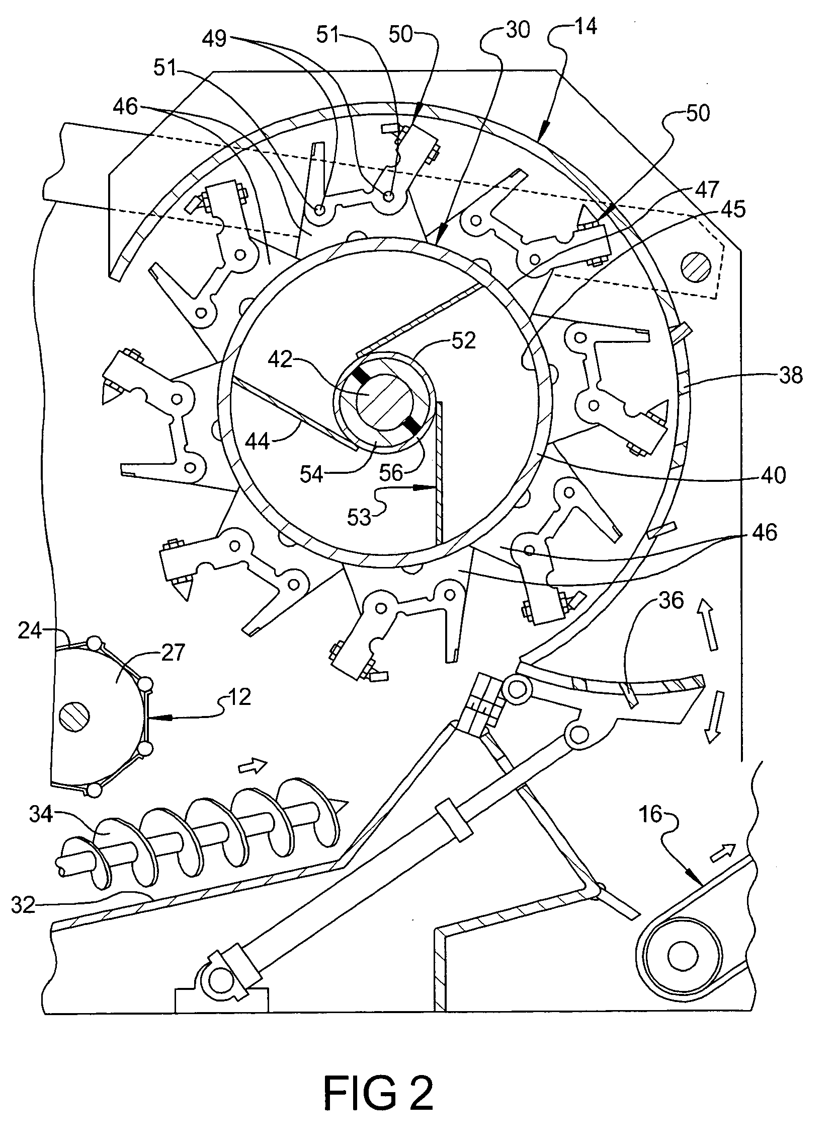
[0022]Referring to FIGS. 1 and 2, the infeed ...


PUM


Abstract

A rotatable assembly for a machine includes a rotatable shaft having a longitudinal axis and a rotatable member disposed about the shaft. The rotatable assembly also includes at least one first connecting member operatively mounted to the rotatable member and to the shaft at a first location along the longitudinal axis of the shaft. The rotatable assembly includes at least one second connecting member operatively mounted to the rotatable member and located at a second location spaced from the first location along the longitudinal axis of the shaft. The rotatable assembly further includes a bearing operatively mounted to the shaft, wherein the second connecting member is operatively mounted to the bearing to allow the shaft to twist without permanent deformation when a concentrated load is subjected to the shaft as the rotor is rotated.

Description

CROSS-REFERENCE TO RELATED APPLICATION(S)[0001]The present application claims the priority date of co-pending U.S. Provisional Patent Application Ser. No. 60 / 558,053, filed Mar. 31, 2004.BACKGROUND OF THE INVENTION[0002]1. Field of the Invention[0003]The present invention relates generally to rotatable members for machines and, more particularly, to a rotatable assembly for a machine.[0004]2. Description of the Related Art[0005]It is known to provide a machine such as a waste processing machine to reduce waste material. The waste processing machine typically includes a rotatable assembly such as a rotor assembly. The rotor assembly generally includes a rotor and a plurality of processing tools attached to the rotor for reducing the waste material as the rotor rotates. An example of such a waste processing machine is disclosed in U.S. Pat. No. 5,863,003 to Smith. In that patent, the rotor assembly comprises a generally cylindrical rotor onto which a plurality of processing tools is m...

Claims


Application Information

Patent Timeline
Patent Type & Authority Patents(United States)
IPC IPC(8): B02C13/286
CPCB02C18/16B02C13/26
Inventor SMITH, LEWARD NILE
Owner SMORACY
Why Eureka
Try Eureka