Embedding element to be embedded in the end part of a windmill blade, a method producing such an embedding element as well as embedding of such embedding elements in a windmill blade

a technology of embedding elements and windmill blades, which is applied in the direction of propulsive elements, water-acting propulsive elements, propellers, etc., can solve the problems of weakening strength, time-consuming positioning, troublesome fastening of fibre composite components, etc., and achieves the effect of facilitating the positioning of elements

Inactive Publication Date: 2007-01-16
LM GLASSFIBER
View PDF5 Cites 56 Cited by
  • Summary
  • Abstract
  • Description
  • Claims
  • Application Information

AI Technical Summary

Benefits of technology

[0006]The object of the invention is to provide a new and improved embedding element for embedment in a wind turbine blade made of fibre composite material allowing for a simplified embedment process and ensuring increased strength at fixation of the wind turbine blade to the turbine hub.
[0008]According to an embodiment the embedding element may have a tapering shape in the direction towards the second end, whereby the fibre lay-up may be performed during the embedding process without causing sharp bends in the fibres or fibre mats in the transitional area between the second end of the embedding element and the composite component. If the rigidity of the embedding element differs from that of the fibre composite material, a gradual transition in the rigidity of the finished fibre composite component is also obtained.
[0011]The invention also relates to a method of producing the above embedding element, wherein an elongated core element, preferably of a fibre composite material and preferably made by pultrusion, is provided, a fastening member being arranged at the first end of the core element and the core element with the fastening member being secured inside a casing by means of adhesion, said casing including the concave and the convex lateral faces and preferably made of a fibre composite material, preferably by pultrusion. A solid embedding element may thus be produced in a simple manner by means of such a method.
[0012]According to a preferred embodiment of the method the first end of the core element is conical and the inwardly facing end of the fastening member is provided with a corresponding conical recess or vice versa. As a result, the two parts may be accurately fixed in relation to each other and the embedding element is provided with a strong fixation and increased strength.
[0013]According to an advantageous embodiment two embedding elements are produced simultaneously by arranging a fastening member at either end of the core element prior to the encasement thereof inside the casing, and subsequently making an inclined, plane cut from the upper face to the lower face or vice versa to produce two wedge-shaped embedding elements. This method offers a particularly simple manufacture of wedge-shaped embedding elements and is also advantageous in that safety checks may be carried out by measuring the tensile strength through the fastening means in both end portions and in that a tensile test may be performed before the two elements are separated.

Problems solved by technology

The fastening of fibre composite components, eg polymer components of fibre glass or carbon fibres, which are subjected to loads from other structural elements, is often troublesome.
One of these problems occurs when a wind turbine blades is to be secured to the hub of the wind turbine in such a manner that the connection therebetween is able to transfer heavy dynamic forces.
One drawback of this method is that it is time-consuming to position the embedding elements accurately in the mould and subsequently thereto place fibre mats in abutment with the element to ensure a durable embedment.
Due to the circular shape of the rods, the fibre mats have to be pushed downwards on either side, and even if this is achieved, folds are created in the fibres / fibre mats which weaken the strength and which in turn cause a risk of delamination due to the heavy dynamic loads.

Method used


Image

  • Embedding element to be embedded in the end part of a windmill blade, a method producing such an embedding element as well as embedding of such embedding elements in a windmill blade
  • Embedding element to be embedded in the end part of a windmill blade, a method producing such an embedding element as well as embedding of such embedding elements in a windmill blade
  • Embedding element to be embedded in the end part of a windmill blade, a method producing such an embedding element as well as embedding of such embedding elements in a windmill blade

Examples


Embodiment Construction

[0006]The object of the invention is to provide a new and improved embedding element for embedment in a wind turbine blade made of fibre composite material allowing for a simplified embedment process and ensuring increased strength at fixation of the wind turbine blade to the turbine hub.

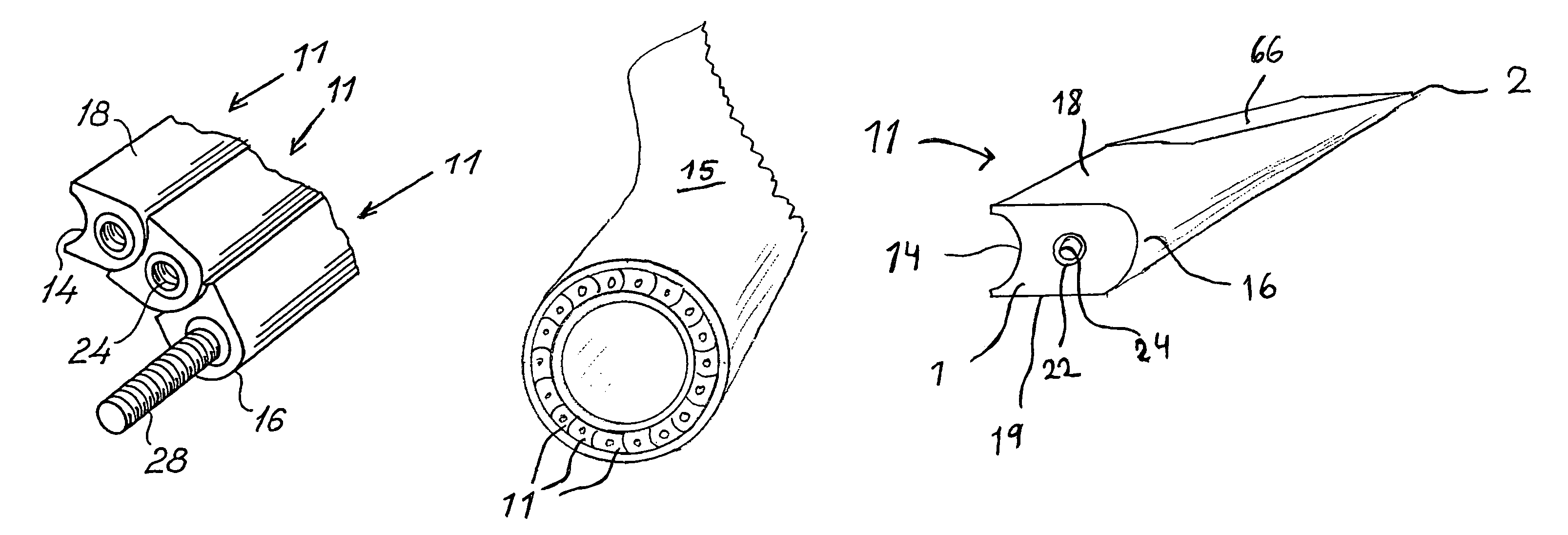
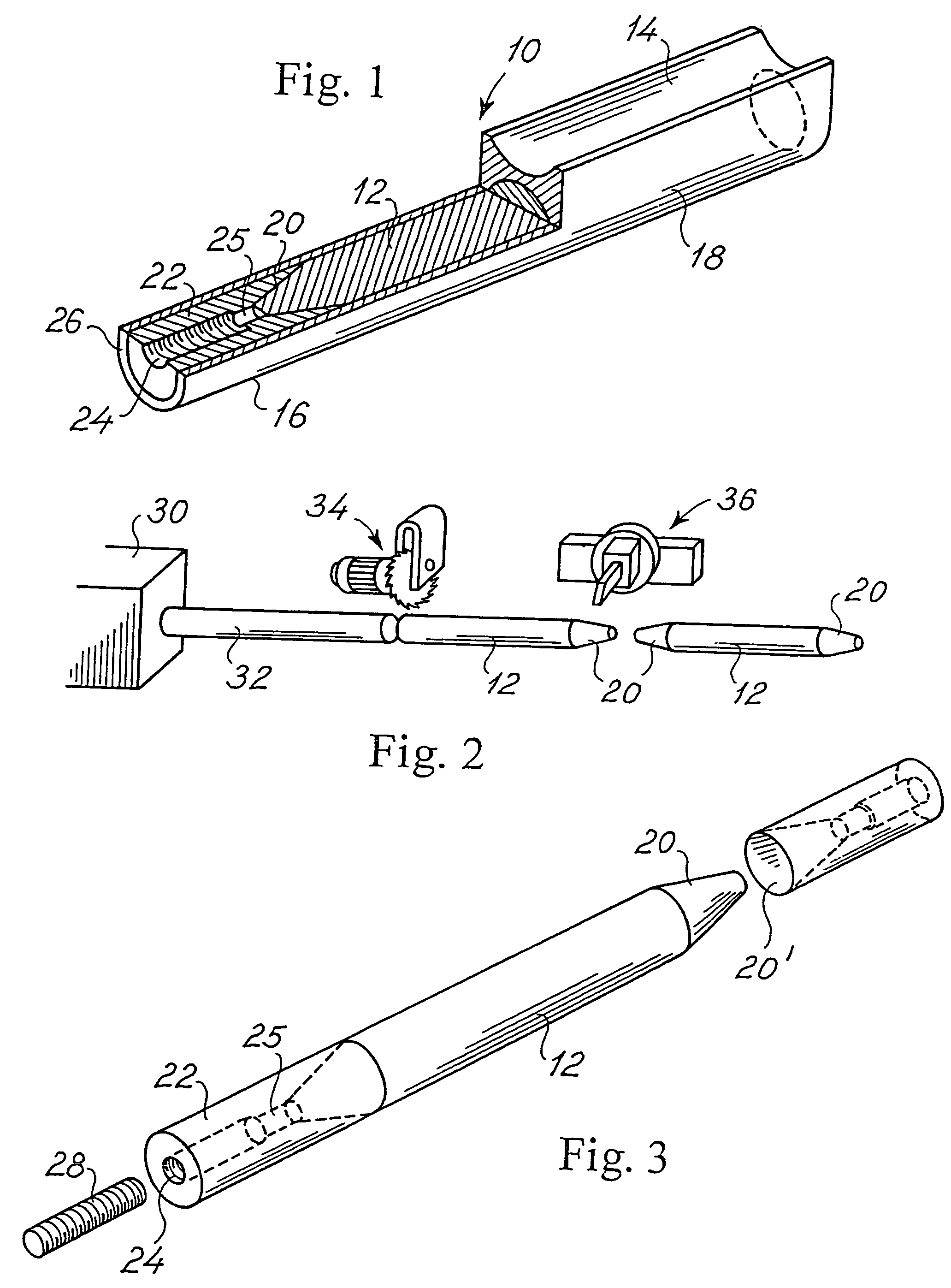
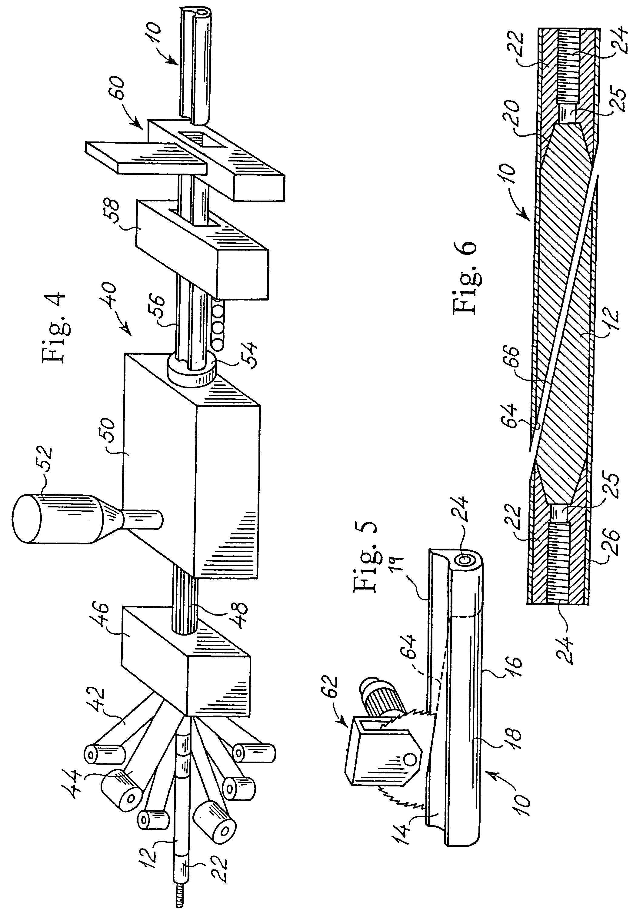
[0007]According to the invention the object is obtained in that between its two end portions the embedding element is provided with a first longitudinal lateral face extending substantially concavely in a cross-sectional view perpendicular to the longitudinal axis of the embedding element, and with a second longitudinal lateral face facing opposite the first lateral face and extending substantially correspondingly convexly in a cross-sectional view perpendicular to the longitudinal axis. As a result it is possible to lay up the embedding elements in alignment such that a concave lateral face engages a convex lateral face, whereby the positioning of the elements is facilitated. Due to the concavity / c...


PUM

PropertyMeasurementUnit
conical shapeaaaaaaaaaa
shapeaaaaaaaaaa
circumferenceaaaaaaaaaa

Abstract

An embedding element (11) for embedment in the root of a wind turbine rotor blade (15) of a fibre composite material, said embedding element being elongated and having a first end portion (1) and a second end portion (2) and provided with fastening means, eg a threaded hole, a threaded rod or the like in its first end portion (1). Between its two end portions (1, 2) the embedding element (11) is provided with a first longitudinal lateral face (14) extending substantially concavely in a cross-sectional view perpendicular to the longitudinal axis of the embedding element, and with a second longitudinal lateral face (16) facing opposite the first lateral face (14) and extending substantially correspondingly convexly in a cross-sectional view perpendicular to the longitudinal axis. The invention further relates to a method of producing such an embedding element, a method of producing a wind turbine blade (15) of fibre composite material, a plurality of embedding elements (11) being embedded such in juxtaposition in the blade root that they follow the circumference of the root and the concave lateral face (14) of each embedding element (11) engaging the convex lateral face (16) of a juxtaposed embedding element and allowing access to the fastening means (24) from the outside.

Description

TECHNICAL FIELD [0001]The invention relates to an embedding element for embedment in the root of a wind turbine rotor blade, said element being elongated and having a first end portion and a second end portion and provided with fastening means, eg a threaded hole, a threaded rod or the like in its first end portion.[0002]The invention further relates to a method of producing such an embedding element, a method of producing a wind turbine rotor blade, in which a plurality of embedding elements are embedded, and a wind turbine rotor blade.BACKGROUND ART [0003]The fastening of fibre composite components, eg polymer components of fibre glass or carbon fibres, which are subjected to loads from other structural elements, is often troublesome. One of these problems occurs when a wind turbine blades is to be secured to the hub of the wind turbine in such a manner that the connection therebetween is able to transfer heavy dynamic forces. The end face of a rotor blade root is often circular a...

Claims


Application Information

Patent Timeline
Patent Type & Authority Patents(United States)
IPC IPC(8): F03D11/00B29C70/52B29C70/86B29K105/08F03D1/06
CPCB29C70/525F03D1/0658B29C70/86Y02E10/721Y02E10/72Y02P70/50
Inventor KILDEGAARD, CASPER
Owner LM GLASSFIBER
Why Eureka
Try Eureka