Real time monitoring of CMP pad conditioning process

a technology of conditioning process and polishing pad, which is applied in the direction of grinding/polishing apparatus, grinding machine components, grinding/polishing machines, etc., can solve the problems of affecting the performance of polishing pads, affecting the efficiency of conditioning disks, and affecting the efficiency of polishing pads, etc., to prolong the life of facilitate detection of abnormal conditioner disks. , the effect of prolonging the life of both polishing pads and conditioner disks

Inactive Publication Date: 2007-01-16
TECH SEMICON SINGAPORE PTE
View PDF10 Cites 20 Cited by
  • Summary
  • Abstract
  • Description
  • Claims
  • Application Information

AI Technical Summary

Benefits of technology

[0013]Still another object of at least one embodiment of the present invention has been to make said process and apparatus easy to implement using any available CMP tool set.
[0014]A further object of at least one embodiment of the present invention has been to prolong the lives of both polishing pads and conditioner disks.
[0015]A still further object of at least one embodiment of the present invention has been to facilitate detection of abnormal conditioner disks thereby averting possible future damage to wafers by the CMP process.

Problems solved by technology

A problem with CMP processing is that the throughput may drop because waste particles accumulate at the surface of the polishing pad.
The conditioning disks themselves may eventually lose their effectiveness by being worn down or by getting plugged up with particulate matter.
If a change in effectiveness is not detected, preferably during the conditioning process itself, a sub-standard polishing pad may be inadvertently returned to service, with undesirable consequences.
Furthermore, it is very difficult to achieve good repeatability for the conditioning process if the manual adjustment is performed by different operators.
Although the final objectives of all the prior art cited above are similar, none of them mount their sensor on the conditioner support arm nor do they use the measurement and application of vibration signals from the pad conditioner for real-time monitoring and control of the conditioning process.

Method used


Image

  • Real time monitoring of CMP pad conditioning process
  • Real time monitoring of CMP pad conditioning process
  • Real time monitoring of CMP pad conditioning process

Examples


Embodiment Construction

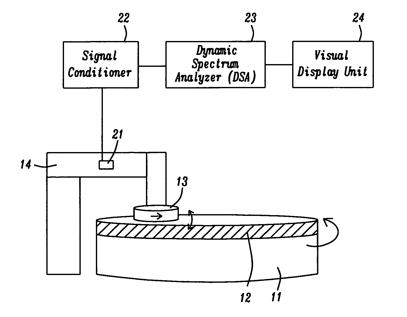
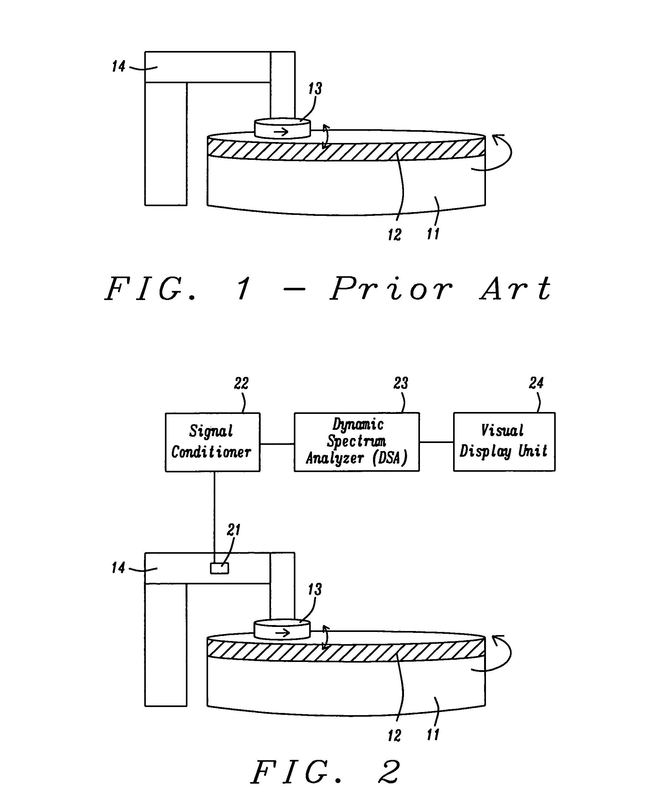
[0025]The apparatus of the present invention is schematically illustrated in FIG. 2. It includes vibration sensor 21, signal conditioner 22, dynamic spectrum analyzer 23, and visual display unit 24. Our preferred device for vibration sensing has been an accelerometer (for reasons that will be explained below) but related devices such as microphones, reflectometers, Linear Variable Displacement Transformer (LVDT), Strain Gauge, Proximeter (magnetic and inductive), and Laser Vibrometer could also have been used without departing from the spirit of the invention.

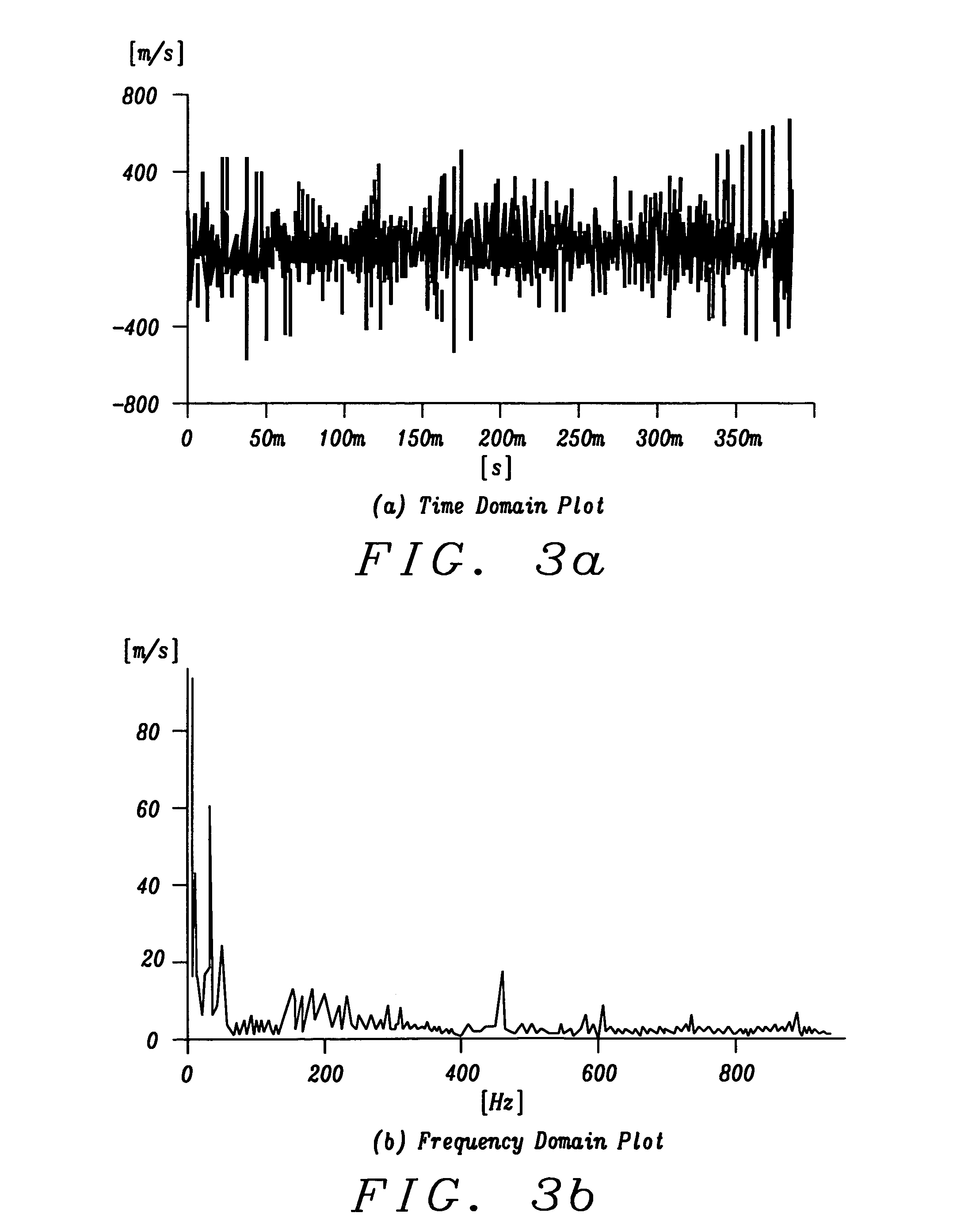
[0026]Sensor 21 is mounted on support arm 14 of pad conditioner 13. The signal detected by the sensor 21 corresponds to vibrational velocity as a function of time, being therefore a time domain representation. It is amplified by signal conditioner 22 which may be either a Constant Current Line Drive (CCLD) or a charge amplifier. If the CCLD version is selected it may be built-in together with the Dynamic Spectrum Analyser (DSA)...


PUM

PropertyMeasurementUnit
frequencyaaaaaaaaaa
frequenciesaaaaaaaaaa
pressureaaaaaaaaaa

Abstract

CMP pad conditioning processes have been monitored and controlled by detecting the vibrational spectrum of a sensor mounted on the conditioner support arm. An accelerometer is used as the detector so that vibrational velocity (which correlates with pad wear) can be measured, rather than displacement or acceleration. After the vibrational spectrum has been transformed to its frequency domain equivalent, it is monitored for the presence of abnormal peaks in order to control the conditioning process.

Description

FIELD OF THE INVENTION[0001]The invention relates to the general field of chemical-mechanical polishing (CMP) with particular reference to conditioning the polishing pads after extended use.BACKGROUND OF THE INVENTION[0002]CMP has, for many years, been the preferred method for planarizing integrated circuits. As its name implies, this process involves mechanical polishing assisted by chemical action. In CMP, wafers are mounted on a suitable holder and then pressed against a polishing pad that has been attached to a rotating platen. A problem with CMP processing is that the throughput may drop because waste particles accumulate at the surface of the polishing pad. To restore the effectiveness of the polishing pads, they are typically ‘conditioned’ by using an abrasive disk to remove the waste matter. Such disks are generally embedded with diamond particles and are mounted so as to be independently moveable and rotatable.[0003]FIG. 1 shows a typical arrangement for a CMP pad condition...

Claims


Application Information

Patent Timeline
Patent Type & Authority Patents(United States)
IPC IPC(8): B24B1/00B24B49/00
CPCB24B53/017B24B49/003
Inventor LIM, KHOON PENGLEE, KOK ENG
Owner TECH SEMICON SINGAPORE PTE
Why Eureka
Try Eureka