
Magnetic recording medium

Inactive Publication Date: 2007-01-16
HITACHI GLOBAL STORAGE TECH JAPAN LTD
View PDF9 Cites 5 Cited by
  • Summary
  • Abstract
  • Description
  • Claims
  • Application Information

AI Technical Summary

Benefits of technology

[0012]An object of the present invention is to provide, at low cost, a longitudinal magnetic recording medium which realizes a high recording density while securing a satisfactory thermal fluctuation resistance and a reduction in defects.

Problems solved by technology

However, when the volume of a crystal particle becomes extremely small, due to refinement of the magnetic crystal particles, the magnetic crystal particles are susceptible to thermal energy even at an ordinary temperature, so that recorded magnetization decays over time.
However, since Ru is very expensive and should be used in a ratio of 1:1 to Al, the use of Ru entails a remarkable increase in cost of the medium.
Further, in order to increase the thickness of the RuAl seed layer, input power must be increased for sputtering, thereby causing problems of increases in dust and defects.

Method used


Image

  • Magnetic recording medium
  • Magnetic recording medium
  • Magnetic recording medium

Examples


example 1

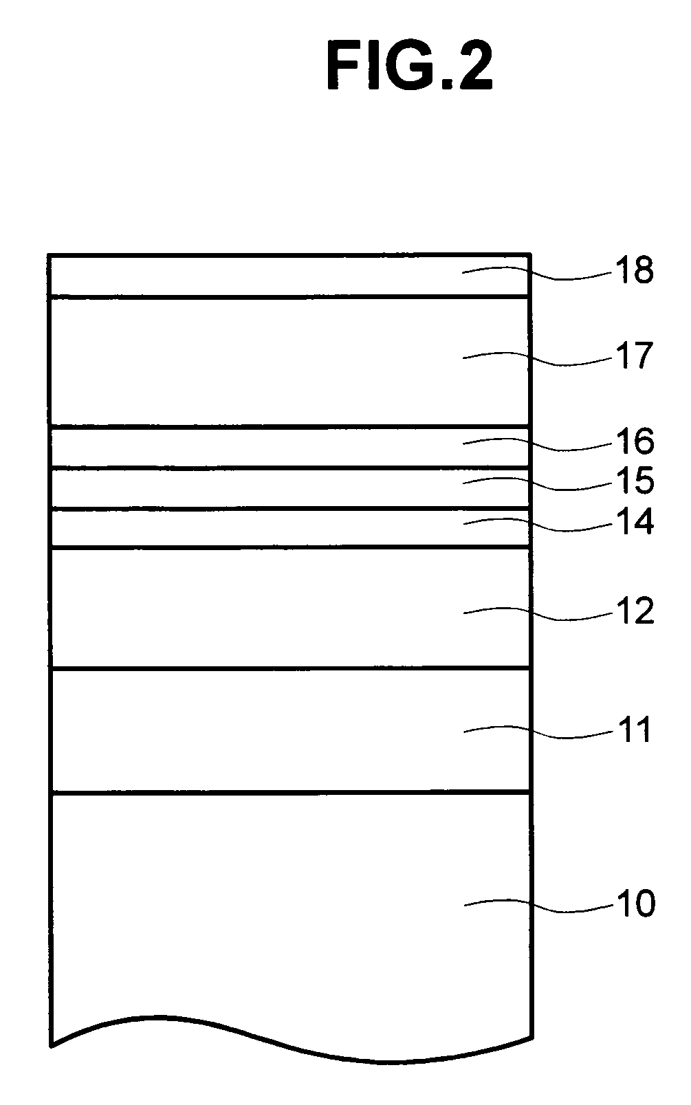
[0040]Experiments were performed to find out the optimum combination for the first seed layer and second seed layer. FIG. 2 is a sectional view of longitudinal magnetic recording media used for the experiments. The layer structures of the media are described below. Each of the layers was formed by DC magnetron sputtering using the so-called single-wafer sputtering apparatus, which is capable of forming each of the layers in individual sputtering chambers. Ar was used as the main sputtering gas.

[0041]A first seed layer 11 composed of Ti and 52% atomic weight of Al (TiAl0.25) and having a thickness of 30 nm was formed on a glass substrate 10 having an outer diameter of 65 mm. Then, after heating a surface of the first seed layer 11 with an infrared ray lamp to 300° C., a second seed layer 12 having a thickness of 30 nm was formed. In this case, material of the second seed layer was changed for each of the media. A second underlayer 14 composed of Cr and 20% atomic weight of Mo (CrMo0....

example 2

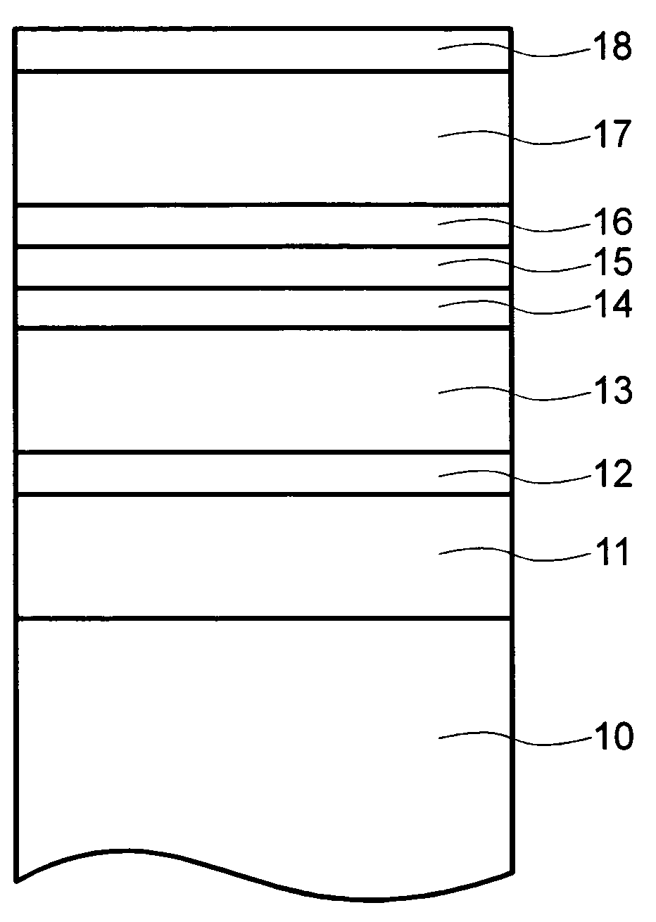
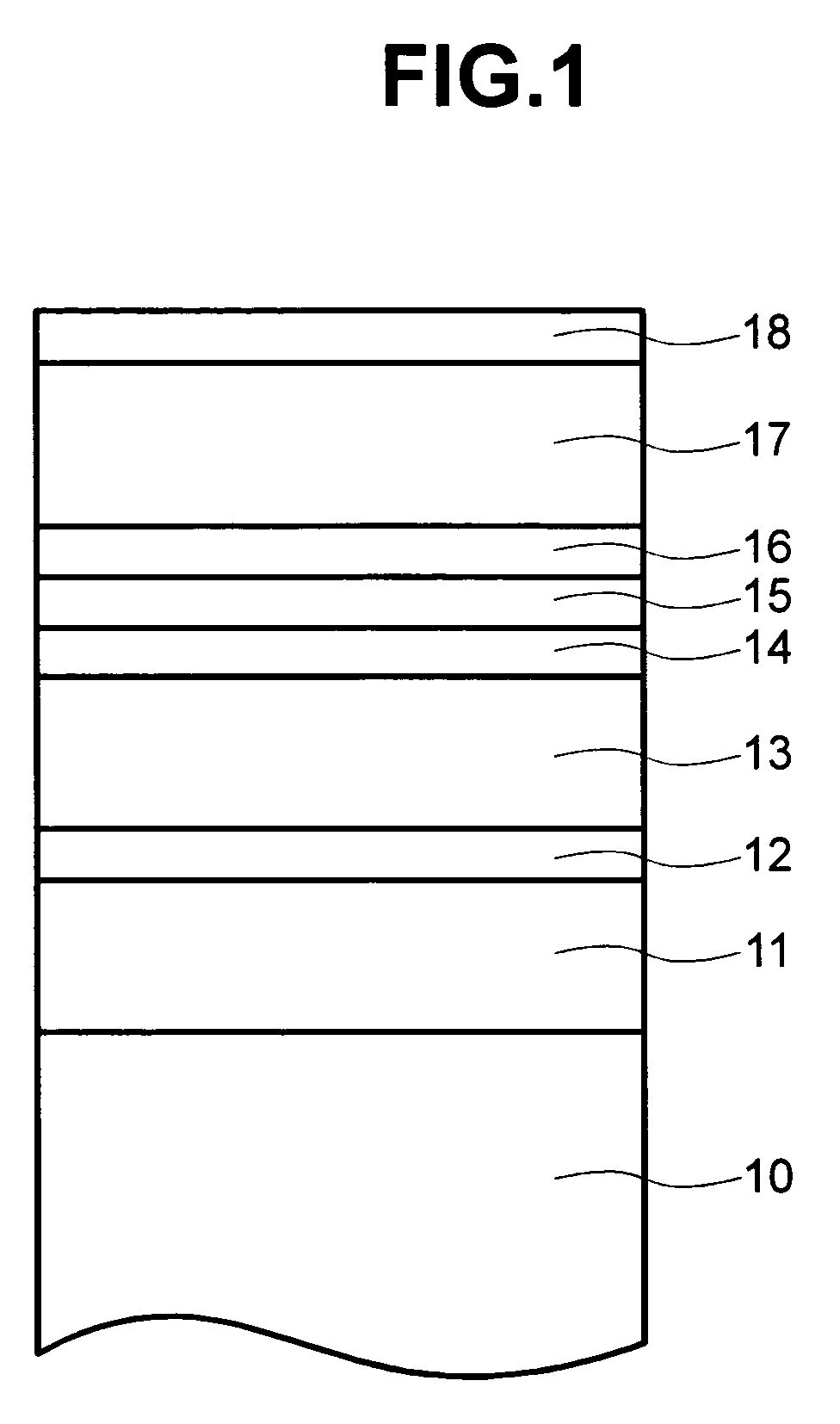
[0058]A layer structure of a medium of this example is now described with reference to the sectional view of FIG. 1. A first seed layer formed of Cr, 35% atomic weight of Ti, and 10% atomic weight of Ta first seed layers 11 was formed on a glass substrate 10 having an outer diameter of 65 mm. The thickness of the first seed layer was changed for the experiments. A surface of first seed layer 11 was heated with an infrared ray lamp with its power set to 2.18 kW, and then a Cr second seed layer 12 having a thickness of 5 nm was formed on first seed layer 11. On the second seed layer, a Co, 25% atomic weight of Al, and 25% atomic weight of Ti was used as a first underlayer 13 having a thickness of 30 nm and a composition of Cr and 20% atomic weight of Mo was used as a second underlayer 14 having a thickness of 5 nm were formed in this order. Formed on the second underlayer 14 was a composition of Co, 14% atomic weight of Cr, and 4% atomic weight of Pt as a lower magnetic layer 15, a Ru...


PUM


Abstract

A large-capacity, low-cost, longitudinal magnetic recording medium capable of ultra-high-density recording of 70 Gigabits or more per square inch is disclosed. The longitudinal magnetic recording medium of the present invention comprises a first seed layer, a second seed layer, a first underlayer, a second underlayer, and a magnetic layer, which are formed on a nonmagnetic substrate in this order. A material containing at least Al and any one of Ru and Re is used to form the second seed layer, and a material containing at least any one of Co and Ni and one or both of Al and Ti is used to form the first underlayer. It is also possible to use Cr or a Cr alloy containing Cr and at least one element selected from the constituent element group A consisting of Ti, Mo, and W for forming the second seed layer.

Description

CROSS REFERENCE TO RELATED APPLICATIONS[0001]This application is related to an claims priority from Japanese Application No. 2003-118582, filed Apr. 23, 2003.BACKGROUND OF THE INVENTION[0002]The present invention relates to longitudinal magnetic recording media, such as magnetic drums, magnetic tapes, magnetic disks, and magnetic cards, and magnetic recording devices. In particular, the present invention relates to a longitudinal magnetic recording medium suitably used for ultrahigh-density recording of 70 Gigabits or more per square inch.[0003]Owing to popularization of the Internet vis-à-vis the World Wide Web (WWW), the demand for magnetic disk devices is increasing along with the increase in the number of personal computers on the market. Although it is possible to access the Internet from mobile terminals as well as from personal computers, it is necessary to incorporate a magnetic disk device into a mobile terminal to pursue further convenience of the mobile terminals. It is e...

Claims


Application Information

Patent Timeline
IPC IPC(8): G11B5/66G11B5/738G11B5/73H01F10/30
CPCG11B5/7325G11B5/732G11B5/66G11B5/7379G11B5/7369
Inventor YAMAMOTO, TOMOOYAHISA, YOTSUOHINOUE, TATSUYAKASHIWASE, HIDEKAZUKANBE, TETSUYASUZUKI, HIROYUKI
Owner HITACHI GLOBAL STORAGE TECH JAPAN LTD
Learn More