Method of cutting an object and of further processing the cut material, and carrier for holding the object and the cut material

a technology of object and cut material, which is applied in the direction of basic electric elements, electrical equipment, welding apparatus, etc., can solve the problems of high wear on the saw blade, chip fracture, and high breakout at the upper and lower edges of the chips

Inactive Publication Date: 2007-01-16
SYNOVA SA
View PDF12 Cites 95 Cited by
  • Summary
  • Abstract
  • Description
  • Claims
  • Application Information

AI Technical Summary

Benefits of technology

[0006]The carrier can then be transparent or non-transparent to the laser radiation. If a non-transparent carrier is used, then this is attacked by the laser radiation. However, the laser intensity will be selected in such a way that there is only a slight removal of material from the carrier. A small cut groove will then result in the cut. However, this cut groove prevents water passing between the carrier and the cut material.
[0016]Instead of a flexible mat, a transparent plate can also be used as the carrier. The laser beam then passes through the plate without processing it. The water leaves the cut gap in its cutting direction. This method is particularly suitable for very thin, that is to say fragile chips or wafers. Identification of the chips by means of laser radiation (laser marking) on the rear of said chips can also be performed through the transparent plate. Since the carrier plate is not attacked, it can be used again and again. As a result of this laser marking, tracking of the individual chips during the subsequent processing is possible.

Problems solved by technology

Furthermore, breakouts often occurred at the upper and lower edge of the chips.
Cracks could also arise, which then led to fracture of the chip.
The wear on the saw blade was high and, in addition, only straight cuts could be carried out.

Method used


Image

  • Method of cutting an object and of further processing the cut material, and carrier for holding the object and the cut material
  • Method of cutting an object and of further processing the cut material, and carrier for holding the object and the cut material

Examples


Embodiment Construction

[0043]In the following text, examples of the carrier according to the invention and of the laser water-jet cutting according to the invention will be explained in more detail using several examples and with reference to the drawings, in which:

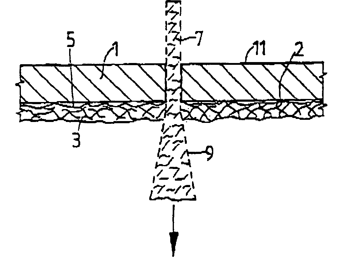
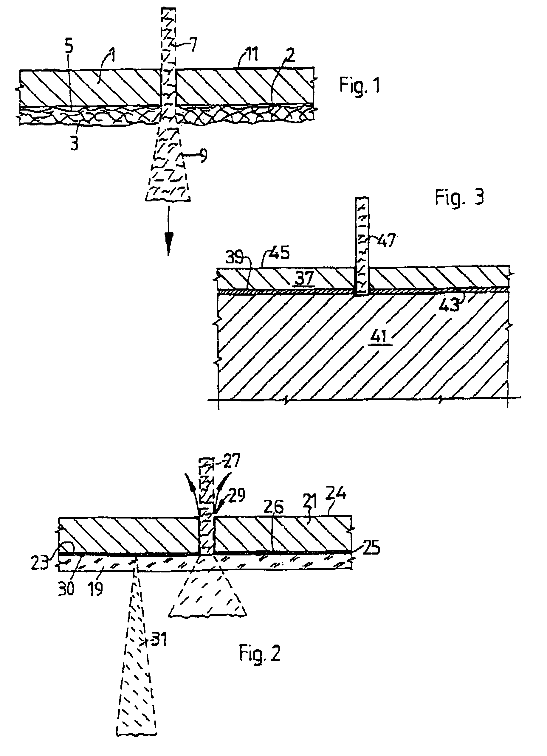
[0044]FIG. 1 shows a cross section through a mat-like carrier with an object adhesively bonded on,

[0045]FIG. 2 shows, analogous to this, a cross section with a plate-like solid carrier and

[0046]FIG. 3 shows a variant of the method illustrated in FIGS. 1 and 2.

WAYS OF IMPLEMENTING THE INVENTION

[0047]FIG. 1 illustrates a silicon wafer 1 with its underside 2 adhesively bonded to a mat 3, in cross section. The “active” upper side 11 of the wafer 1 is free at the top. The mat 3 consists of fiber material covered or impregnated with adhesive. Since this is a fiber material, the surface 5 of the mat 3 is illustrated as irregular. However, it should be noted that this is a great exaggeration. This is because a laser water jet 7 cutting through the wafe...


PUM

PropertyMeasurementUnit
diameteraaaaaaaaaa
diameteraaaaaaaaaa
diameteraaaaaaaaaa

Abstract

The invention relates to an object (1) that is cut by means of a laser and a water beam and to further processing of the cut material. The object is glued on a carrier (3) that is provided with an adhesive and can be transparent for the radiation used in the water beam (7). The carrier can be a solid body and preferably a fibrous mat (3). Said body or mat is penetrated by the water beam. The object (1) or the cut material thereof is held on the carrier (3) before, during and after cutting through in such a way that said object or material does not change position. In a preferred embodiment, a silicon wafer is used as the object because of the high cutting exactness to be obtained. Other materials can also be used.

Description

[0001]This application is the national phase under 35 U.S.C. §371 of PCT International Application Ser. No. PCT / CH01 / 00218 which has an International filing date of Apr. 4, 2001, which designated the United States of America.[0002]The invention relates to a method for the laser water-jet cutting of an object as claimed in patent claim 1 and a carrier which can be used in the method as claimed in patent claim 6.PRIOR ART[0003]On a silicon wafer there is a large number of chips (“dies”) which, during and after the separation process, have had to be held in their original position as individual chips, in particular during further processing and treatment. For this purpose, before the separation of the chips, the silicon wafer has been bonded onto a carrier. The chips were then cut out with a saw. For the purpose of cutting out, the cutting depth of a diamond disk was set in such a way that the wafer was cut through completely but the carrier was cut only slightly. The known separating ...

Claims


Application Information

Patent Timeline
Patent Type & Authority Patents(United States)
IPC IPC(8): H01L21/46B23K26/10B23K26/146B23K101/40H01L21/00H01L21/301
CPCH01L21/67092B23K26/1417B23K26/146
Inventor RICHERZHAGEN, BERNOLD
Owner SYNOVA SA
Why Eureka
Try Eureka