Multi-tube fluorescent discharge lamp

a fluorescent discharge lamp and multi-tube technology, which is applied in the manufacture of electric discharge tubes/lamps, transit-tube vessels/containers, electrode systems, etc., can solve the problems of slower vaporization caused by electric flux hitting the cathode and longer life cycle of the cathode, so as to improve the stimulating effect of the fluorescent coating, reduce the size of the cross-section area, and improve the effect of electron flux density

Inactive Publication Date: 2007-01-16
LEE WEN TSAO
View PDF3 Cites 6 Cited by
  • Summary
  • Abstract
  • Description
  • Claims
  • Application Information

AI Technical Summary

Benefits of technology

[0010]This Invention is a multi-tube fluorescent discharge lamp; the design concept of the Invention is made of multiple discharge glass tubes of different calibers in a coaxial structure. By isolating, perforating and blocking the discharge path, and applying phosphor on the surface of the discharge tubes, this creates a thin and transparent film of fluorescent coating, allowing the light of the inner tubes to pass through each of the coatings to the outside of the lamp. In addition, a pair of hot or cold cathodes helps the electronic flux in the vacuum accelerate and hit the Hg molecule, which then create plasma. The coating of the fluorescent on the inner layer surface of the discharge tube is hit by electron ion and emit light. Under the same power rate and with the same lamp volume, the tubes of the multi-tube fluorescent discharge lamp aligned in a coaxial structure have a smaller cross-section area than that of a conventional fluorescent discharge lamp to allow higher density of electron flux to pass through the discharge path in the tubes. Therefore, the high-density electron ion has better stimulating effects on the fluorescent coating and the luminous fluorescent area is larger than conventional fluorescent discharge lamp, both of these advantages increase the luminous flux.
[0011]Compared to conventional fluorescent discharge lamp of the same power rate, this Invention is characterized by higher luminance, lower consumption of electricity and lower heat rate. Moreover, because the electric flux of the Invention is less than that of a conventional fluorescent discharge lamp, the vaporization caused by electric flux hitting the cathode is slower and the life cycle of the cathode is longer than that of conventional fluorescent discharge lamps. It is also feasible to apply a ringed cathode to increase the surface area of the hitting electron flux and then disperse the hitting, so that the oxide material on the surface of the cathode can be protected from rapid consumption. In this way, multi-tube fluorescent discharge lamp can outlive conventional fluorescent discharge lamps.
[0013]The multi-tube fluorescent discharge lamp is designed with coaxial structure, aiming to achieve special color luminance or a balanced spectrum range of light by way of filtering the luminance released from the transparent discharge glass tube of different colors.

Problems solved by technology

Moreover, because the electric flux of the Invention is less than that of a conventional fluorescent discharge lamp, the vaporization caused by electric flux hitting the cathode is slower and the life cycle of the cathode is longer than that of conventional fluorescent discharge lamps.

Method used


Image

  • Multi-tube fluorescent discharge lamp
  • Multi-tube fluorescent discharge lamp
  • Multi-tube fluorescent discharge lamp

Examples


Embodiment Construction

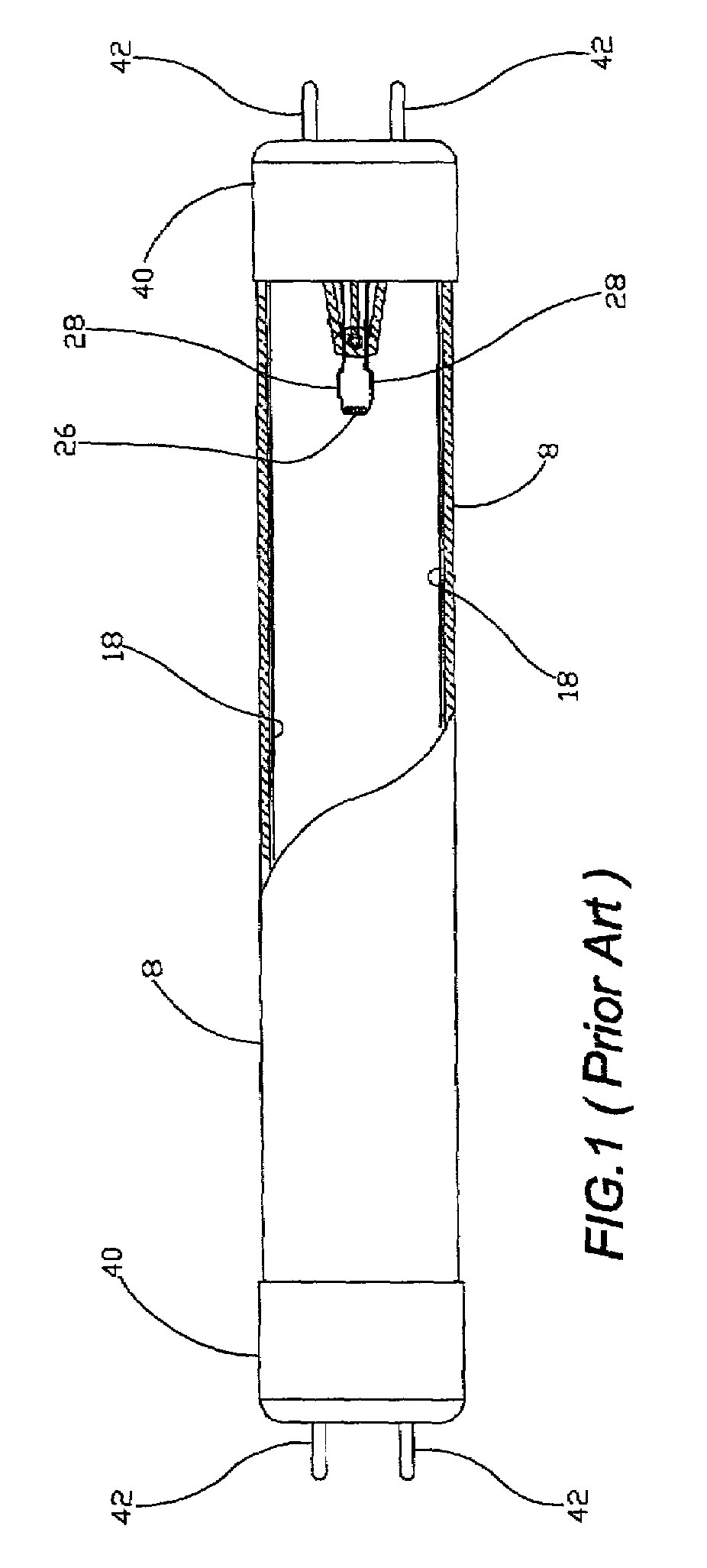
[0040]According to FIG. 1, illustrates a conventional fluorescent discharge lamp. The discharge tube 8 is a straight glass tube. One cathodes 26, with its electrode 28 connected to the terminal 42 on the tube base 40, is located at each end of the tube. The figure shows clearly that there is only one phosphor layer 18 on the inside surface of the tube. In addition, because the density of electronic flux is higher at the axis of the discharge tube than at the phosphor layer 18 on the inside surface, much of the energy around the axis in the discharge tube will be wastefully converted into heat. Therefore, the power conversion factor of the lumen leaves some room for improvement.

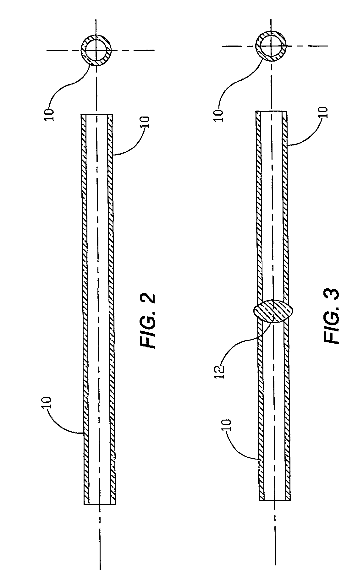
[0041]According to FIG. 2, the first tube 10 is a round straight glass tube positioned at the innermost part of the multi-tube fluorescent discharge lamp. It is where the cathodes 26 as shown in FIG. 1 are to be inserted.

[0042]According to FIG.3, toward the middle of the first tube 10, the glass is softened by...


PUM

PropertyMeasurementUnit
pressureaaaaaaaaaa
vacuumaaaaaaaaaa
transparentaaaaaaaaaa

Abstract

A multi-tube fluorescent discharge lamp, which is constructed of multiple glass tubes of different caliber in coaxial structure, the both sides of the inner most tube are connected to a cathode respectively, by isolating, perforating and blocking the discharge path, forming a successive discharge path, and coating phosphor on surface of the discharge tubes. The Invention can then have more fluorescent area than a conventional fluorescent lamp of the similar size and higher lumen as well as power transfer factor. Compared with the power consumption of a conventional fluorescent discharge lamp, the Invention therefore has higher luminous flux.

Description

BACKGROUND OF INVENTION[0001]1. Field of the Invention[0002]The Invention relates to fluorescent discharge lamps, and more particularly, to a multi-tube fluorescent discharge lamp which construct multiple glass tubes of different caliber in coaxial structure, both ends of the inner most tube are connected to a cathode respectively isolating, perforating and blocking the discharge path, to form a succession of interconnected discharge chambers, and coating fluorescent material on surface of the discharge tubes. Such an Invention can then have more fluorescent area than a conventional fluorescent lamp of similar size and have higher lumen as well as power conversion efficiency. By comparing with the power consumption of a conventional fluorescent discharge lamp, it is therefore has higher luminous flux.[0003]2. Description of the Prior Art[0004]A conventional fluorescent discharge lamp generally is straight or circular tube type. In order to minimize the size and increase luminosity, ...

Claims


Application Information

Patent Timeline
Patent Type & Authority Patents(United States)
IPC IPC(8): H01J17/16H01J61/34H01J23/12C03B23/207C03C17/00H01J9/24H01J9/38H01J61/30H01J61/72H01J61/92
CPCC03B23/207C03C17/003H01J9/245H01J61/92H01J61/30H01J61/72H01J9/38
Inventor LEE, WEN-TSAO
Owner LEE WEN TSAO
Why Eureka
Try Eureka