Actuator for a fluid valve

Inactive Publication Date: 2007-01-16
PARKER HANNIFIN GMBH & CO KG CHAFTSBEREICH DICHTUNGEN
View PDF2 Cites 9 Cited by
  • Summary
  • Abstract
  • Description
  • Claims
  • Application Information

AI Technical Summary

Benefits of technology

[0026]With respect to the configuration of the coil support, including the coil windings formed thereon, the coil support, which is made of an electrically non-conductive material, e.g. plastic, fabric-based laminate or ceramic, may be provided with coil recesses into which the individual coils are wound. According to one embodiment of the invention, the coils wound into the recesses of the coil support can furthermore be covered with a protective layer to impart a smooth surface to the respective coil support provided with the coils. Such a configuration of the coil support makes it possible to realize very small air gaps between the coil support and t

Problems solved by technology

This configuration accepts the drawback that the magnetic flux provided by the permanent magnet cannot be completely converted into a useful flux to move the coil support, and that the field lines, to a large extent, must overcome a longer path in the air gap next to the pole regions, so that a larger amount of magnetic material is required.
This has not only the drawback of increasing the mass of the coil support that must be moved when the actuator is in operation, but

Method used


Image

  • Actuator for a fluid valve
  • Actuator for a fluid valve
  • Actuator for a fluid valve

Examples


Embodiment Construction

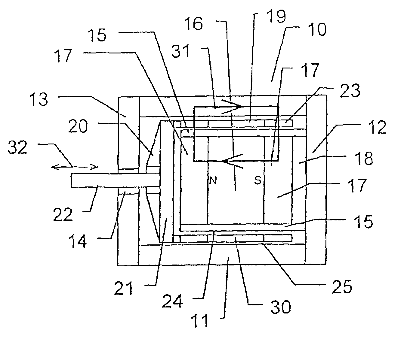
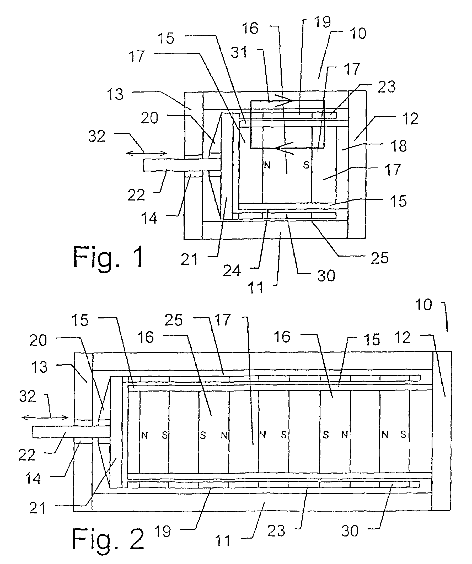
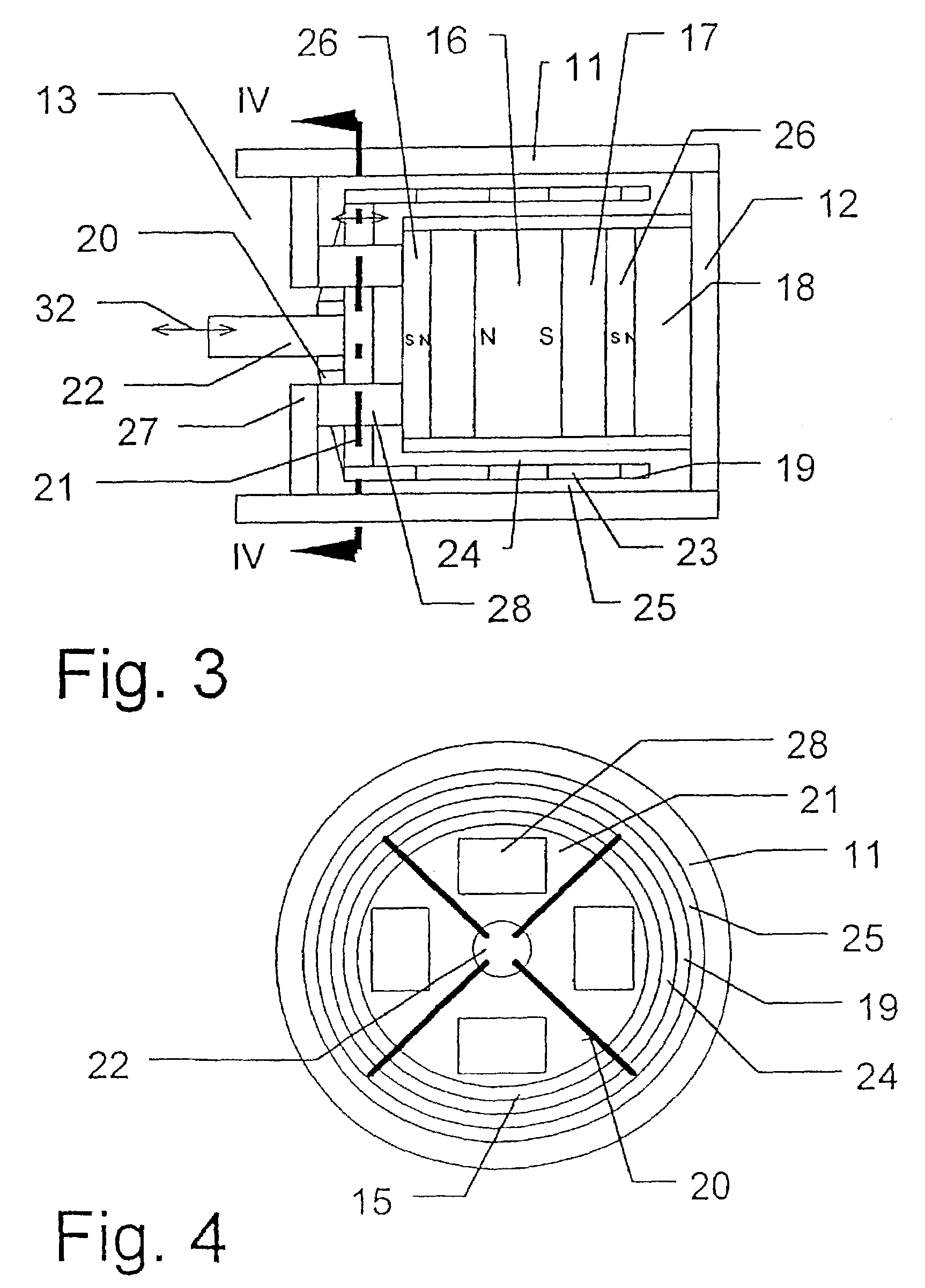
[0036]The actuator shown schematically in FIG. 1 has a housing 10 whose outer housing shell 11 is made of a magnetically conductive material. The closed end face 12 of the housing 10 is made of a different material, i.e. a magnetically non-conductive material, for reasons that will be explained below, while the opposite end face 13 is made of a magnetically conductive material and is provided with a central opening 14.

[0037]A cylindrical magnet tube 15 is arranged in the interior of the housing 10 and connected on one side with the closed end face 12 of the housing 10. The cylindrical magnet tube 15 is made of a magnetically non-conductive material. In its interior a permanent magnet 16 is arranged in a centered position. A pole disk 17 each is disposed on the two end faces of this magnet. Between the pole disk 17 in proximity of the closed end face 12 of the housing 10 and said end face 12, a spacer 18 is furthermore arranged, which is made of a magnetically non-conductive material...


PUM


Abstract

The invention relates to an actuator for actuating a valve installed in a hydraulic or compressed air system comprising a coil support which can be displaced by means of air space induction in a magnetically conducting housing on a magnetic cylinder composed of a permanent magnet and a cylinder pole disk. The invention is characterized in that the dimensions of the permanent magnet and the pole disk correspond to each other in such a way that the diameter of the front surface of the permanent magnet is at least the same size as the circumferential surface of a neighboring pole disk and that the width of the coil associated with the pole disk exceeds the width of the pole disk by the lift amplitude of the coil support. According to the invention, the actuator for actuating a valve used in fluidic engineering is disposed in such a way that the coil support is displaceable in a fluidic medium and the air gap arranged between the coil support and a magnetic cylinder pipe surrounding the permanent magnet and the associated pole disk has a maximum width whereby a laminated lubricating film is formed without displacing the surrounding fluid.

Description

CROSS REFERENCE TO RELATED CASES[0001]This application is a continuation-in-part of U.S. patent application Ser. No. 10 / 416,707; filed Sept. 11, 2003, now U.S. Pat. No. 6,075,195 which is the national phase under Chapter II of International Application No. PCT / / EP01 / 13200, filed Nov. 14, 2001 and which claims priority to German Patent Application No. 100 56 332.56, filed Nov. 14, 2000.BACKGROUND OF THE INVENTION[0002]The invention relates to an actuator for actuating a valve, with a housing shell made of a magnetically conductive material, a coil support that has an actuation projection and is displaceable within the housing shell while forming an air gap relative thereto, with at least one current-carrying coil wound onto its circumference and with a magnet cylinder enclosed by the coil support while forming an air gap, with a sequence of permanent magnet and pole disk made of a magnetically conductive material arranged axially in the cylinder's interior, wherein the axial width of...

Claims


Application Information

Patent Timeline
IPC IPC(8): H01F7/08H01F7/06H02K33/18
CPCH01F7/066Y10T137/8242H01F7/06
Inventor RAUSCH, HARTMUTHBUDIG, PETER-KLAUSWERNER, RALF
Owner PARKER HANNIFIN GMBH & CO KG CHAFTSBEREICH DICHTUNGEN
Why Eureka
Try Eureka