ESD protection circuit

a protection circuit and circuit technology, applied in the direction of electrical equipment, electrical devices, and devices responsive to excess voltage, can solve the problems of false triggering of the esd protection circuit and insufficient margin to avoid false triggering

Active Publication Date: 2007-01-16
APPLE INC
View PDF7 Cites 92 Cited by
  • Summary
  • Abstract
  • Description
  • Claims
  • Application Information

AI Technical Summary

Benefits of technology

[0011]The electrostatic discharge (ESD) protection circuit of the present invention substantially meets these needs and others. In one embodiment, an ESD protection circuit for an integrated circuit includes an ESD clamping circuit, an ESD triggering circuit, and an ESD disabling circuit. The ESD clamping circuit is operably coupled to a first power pin of the integrated circuit and a second power pin of the integrated circuit. The ESD triggering circuit is operably coupled to the ESD clamping circuit, wherein, when enabled and when sensing an ESD event, the ESD triggering circuit provides a clamping signal to the ESD clamping circuit such that the ESD clamping circuit provides a low impedance path between the first and second power pins. The ESD disabling circuit is operably coupled to disable the ESD triggering circuit when the integrated circuit is in a normal operating mode (i.e., is active). Such an ESD protection circuit does not falsely trigger when the integrated circuit is active.

Problems solved by technology

However, with the RC delay set to cover the several hundred nano second ESD event, it may not have sufficient margin to avoid falsely triggering during a normal power up of VDD.
Further, battery operated devices often experience extreme power surges induced by system level ESD / EMI (electromagnetic interference), which may cause the ESD protection circuit to falsely trigger.

Method used


Image

  • ESD protection circuit
  • ESD protection circuit
  • ESD protection circuit

Examples


Embodiment Construction

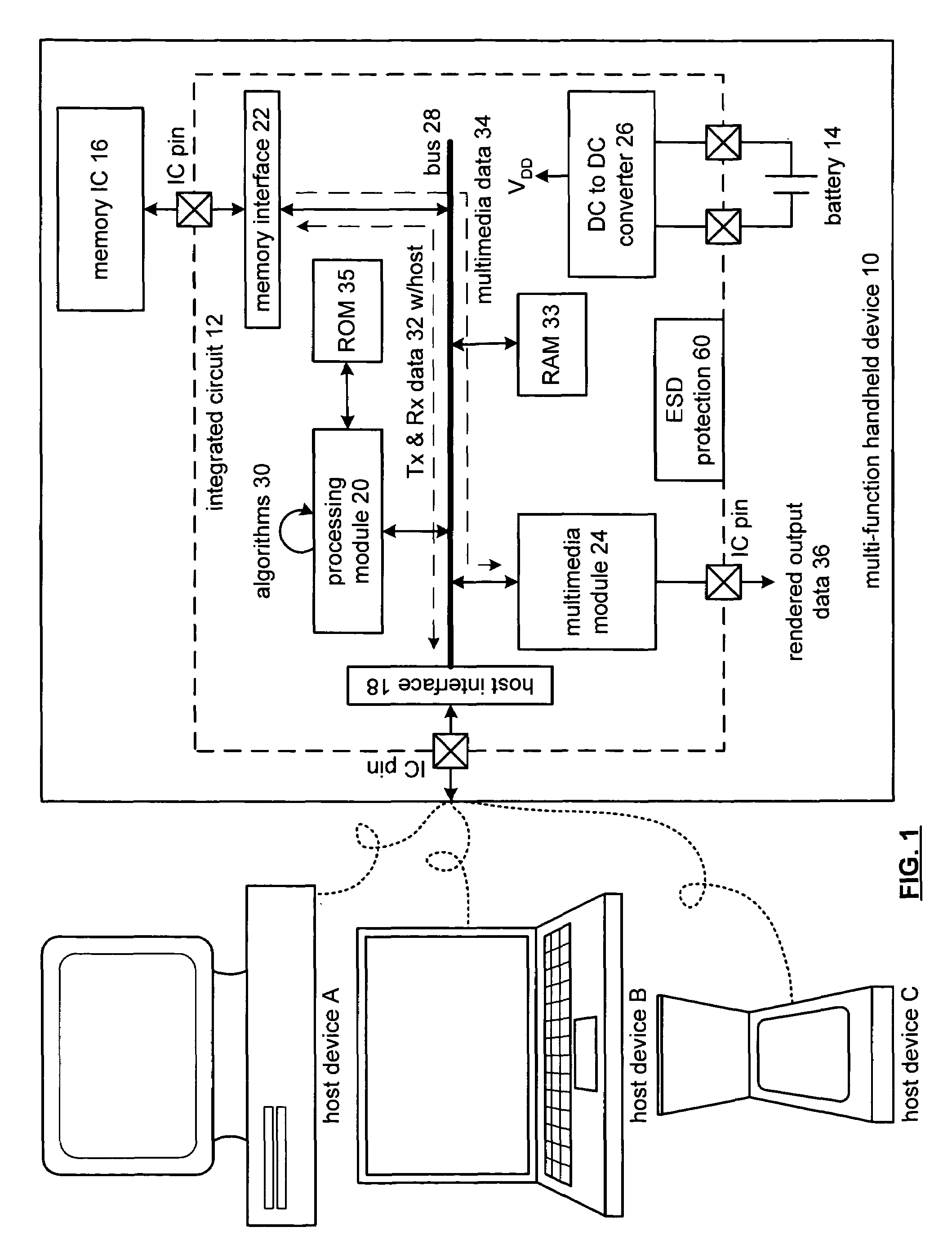
[0020]FIG. 1 is a schematic block diagram of a multi-function handheld device 10 operably coupled to a host device A, B, or C. The multi-function handheld device 10 includes an integrated circuit 12, memory integrated circuit (IC) 16, and a battery 14. The integrated circuit 12 includes a host interface 18, a processing module 20, a memory interface 22, a multimedia module 24, a DC-to-DC converter 26, a bus 28, ESD protection circuit 60 (which will be described in greater detail with reference to FIGS. 3–8), and a plurality of integrated circuit (IC) pins. The multimedia module 24 alone or in combination with the processing module 20 provides the functional circuitry for the integrated circuit 12. The DC-to-DC converter 26, which may be constructed in accordance with the teaching of U.S. Pat. No. 6,204,651, entitled METHOD AND APPARATUS FOR REGULATING A DC VOLTAGE, provides at least a first supply voltage to one or more of the host interface 18, the processing module 20, the multime...


PUM


Abstract

An ESD protection circuit for an integrated circuit includes an ESD clamping circuit, an ESD triggering circuit, and an ESD disabling circuit. The ESD clamping circuit is operably coupled to a first power pin of the integrated circuit and a second power pin of the integrated circuit. The ESD triggering circuit is operably coupled to the ESD clamping circuit, wherein, when enabled and when sensing an ESD event, the ESD triggering circuit provides a clamping signal to the ESD clamping circuit such that the ESD clamping circuit provides a low impedance path between the first and second power pins. The ESD disabling circuit is operably coupled to disable the ESD triggering circuit when the integrated circuit is in a normal operating mode.

Description

CROSS REFERENCE TO RELATED PATENTS[0001]This patent application is claiming priority under 35 USC § 119 to provisionally filed patent application entitled MULTI-FUNCTION HANDHELD DEVICE, having a provisional serial No. of 60 / 429,941, and a filing date of Nov. 29, 2002.BACKGROUND OF THE INVENTION[0002]1. Technical Field of the Invention[0003]This invention relates generally to portable electronic equipment and more particularly to integrated circuits used within such equipment.[0004]2. Description of Related Art[0005]As is known, integrated circuits are used in a wide variety of electronic equipment, including portable, or handheld, devices. Such handheld devices include personal digital assistants (PDA), CD players, MP3 players, DVD players, AM / FM radios, pagers, cellular telephones, computer memory extensions (commonly referred to as thumb drives), etc. Each of these handheld devices includes one or more integrated circuits to provide the functionality of the device. For example, a...

Claims


Application Information

Patent Timeline
Patent Type & Authority Patents(United States)
IPC IPC(8): H02H3/22H01L27/02H02H9/00
CPCH01L27/0251
Inventor TAKEDA, FUJIO
Owner APPLE INC
Why Eureka
Try Eureka