Thin film sensor for brake lining pad wear and brake temperature sensing

a technology of temperature sensing and brake lining, applied in the direction of instruments, force/torque/work measurement apparatus, transportation and packaging, etc., can solve the problem and achieve the effect of increasing the electrical resistance of the modular sensor

Inactive Publication Date: 2007-01-23
INT TRUCK INTPROP LLC
View PDF12 Cites 21 Cited by
  • Summary
  • Abstract
  • Description
  • Claims
  • Application Information

AI Technical Summary

Problems solved by technology

This results in steadily increasing electrical resistance of the modular sensor correlated with wear of the lining.

Method used


Image

  • Thin film sensor for brake lining pad wear and brake temperature sensing
  • Thin film sensor for brake lining pad wear and brake temperature sensing
  • Thin film sensor for brake lining pad wear and brake temperature sensing

Examples


Embodiment Construction

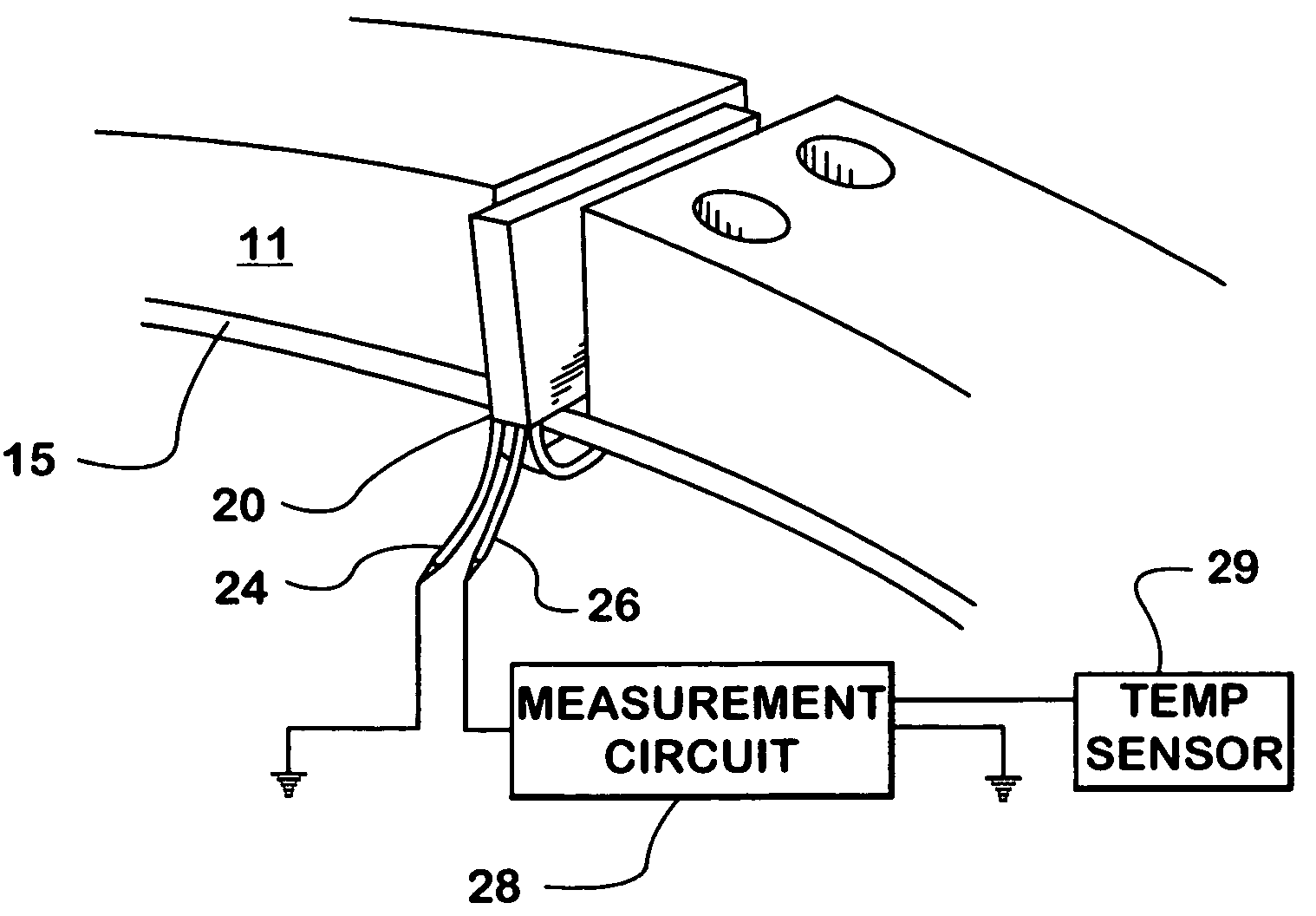
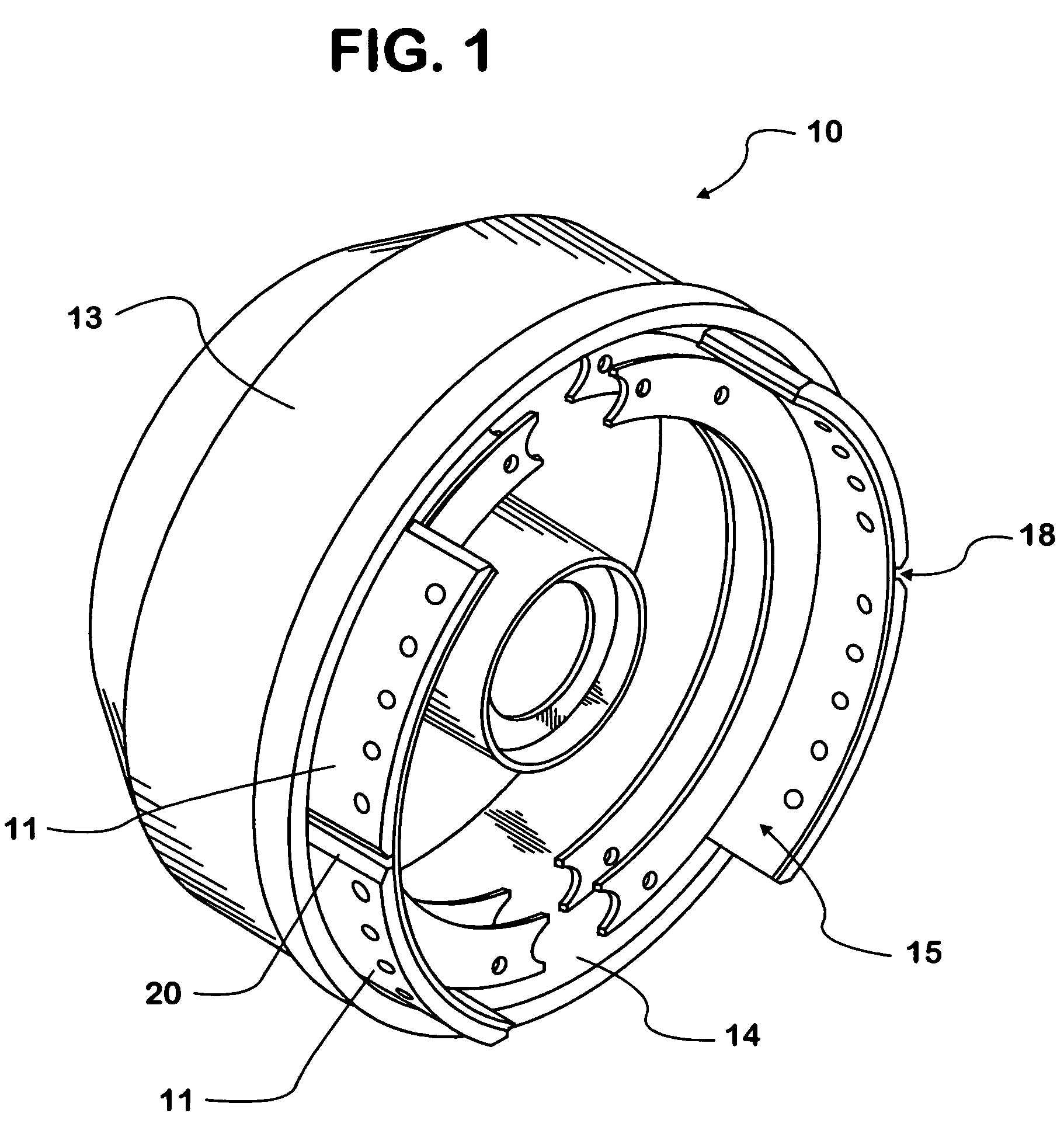
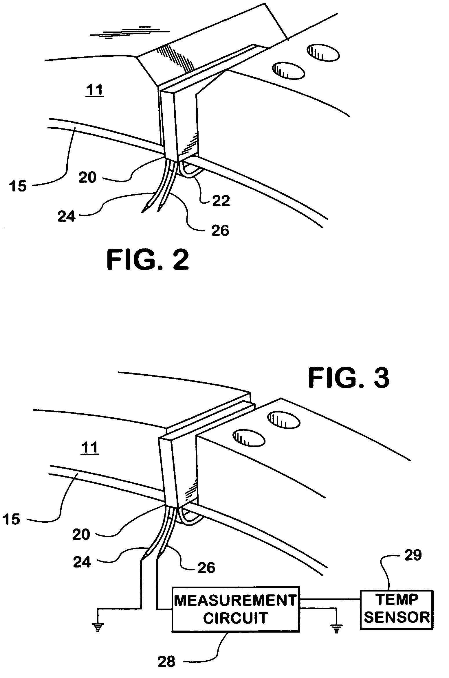
[0018]The present invention is preferably employed in a drum brake assembly 10 as shown in FIG. 1. However, the modular sensor 20 may be adopted for employment in other types of brake assemblies. Referring now to FIG. 1, a brake drum 13 has an inner brake surface 14 for frictionally engaging the brake lining 11. An actuator such as an S-cam arrangement displaces the brake shoes 15 outwardly towards the inner brake surface 14 bringing brake lining 11 into contact with the inner brake surface of the drum 13. Brake linings 11 are mounted to the brake shoe 15 to frictionally engage the brake drum 13 and thus provide braking force. The generic brake drum arrangement 10 and actuation mechanism is completely conventional and is well known in the art.

[0019]Modular sensor 20 is preferably mounted between a pair of brake lining surfaces 11 in a gap 18 with a distal end substantially flush with the outer or friction surface of the brake lining 11. The specific connection of modular sensor 20 t...


PUM


Abstract

A modular electrical resistance sensor is positionable in gaps between brake linings for a drum brake. The modular sensor is worn with the brake linings resulting in steadily increasing electrical resistance of the modular sensor. A measurement circuit associated with the modular sensor is programmed to equate electrical resistance to the degree of wear when the sensor has assumed a steady state temperature at or near the ambient temperature. Otherwise, particularly during periods of use of the brakes, resistance and the degree of wear last calculated become arguments into a function for determining brake lining temperature.

Description

BACKGROUND OF THE INVENTION[0001]1. Technical Field[0002]The invention relates to brake lining wear sensing and brake lining transient temperature detection and more particularly to a modular electrical resistance sensor which may be used to implement wear and temperature sensing.[0003]2. Description of the Problem[0004]Effective brakes are essential to safe motorvehicle operation. Contemporary brake systems dissipate vehicle kinetic energy through brake friction pads as heat. These brake pads have a relatively short service life and require regular replacement. Heavy vehicles have historically exhibited problems with brake overheating, especially when the vehicles are descending along long grades. Overheating reduces stopping ability and accelerates brake pad wear.[0005]Inspection of the brake system has traditionally involved disassembly of the wheel mechanism and visual examination of the pads. It has been recognized that it would be desirable to incorporate some kind of sensor i...

Claims


Application Information

Patent Timeline
Patent Type & Authority Patents(United States)
IPC IPC(8): F16D66/02
CPCF16D66/026F16D2066/001
Inventor PALLADINO, JAMES
Owner INT TRUCK INTPROP LLC
Why Eureka
Try Eureka