Illumination system

a technology of illumination system and insulating strand, which is applied in the direction of contact members penetrating/cutting insulation/cable strand, lighting and heating apparatus, etc., to achieve the effects of low cost manufacturing, convenient and efficient manufacturing and marketing, and durable and reliable construction

Active Publication Date: 2007-01-23
ELECTRALED
View PDF43 Cites 221 Cited by
  • Summary
  • Abstract
  • Description
  • Claims
  • Application Information

AI Technical Summary

Benefits of technology

[0025]It is another object of the present invention to provide a new and improved light emitting diode illumination system which may be easily and efficiently manufactured and marketed.
[0026]It is further an object of the present invention to provide a new and improved light emitting diode illumination system which is of durable and reliable construction.
[0027]An even further object of the present invention is to provide a new and improved light emitting diode illumination system which is capable of low cost manufacture with regard to both materials and labor, and which accordingly is then available for low prices of sale to the consuming public, thereby making such light emitting diode illumination system economically available to the buying public.
[0028]Even still another object of the present invention is to provide a light emitting diode illumination system for the economic and convenient fabrication of a linear, stranded and linked, high-power, high-intensity light emitting diode illumination system.

Problems solved by technology

While these devices fulfill their respective, particular objectives and requirements, the aforementioned patents do not describe an illumination system that allows providing high-power, high-intensity light emitting diode modules that are economic to produce and operate.

Method used


Image

  • Illumination system
  • Illumination system
  • Illumination system

Examples


Embodiment Construction

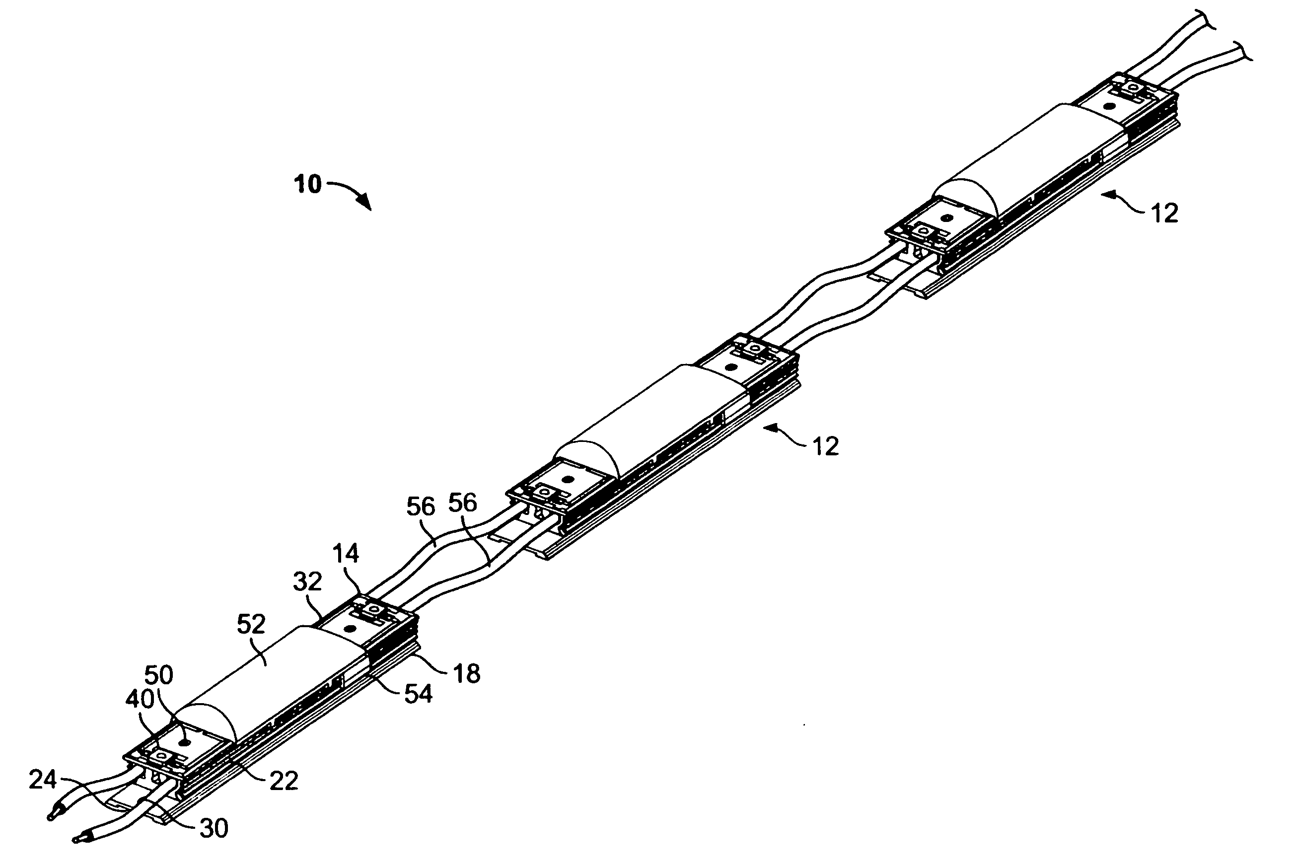
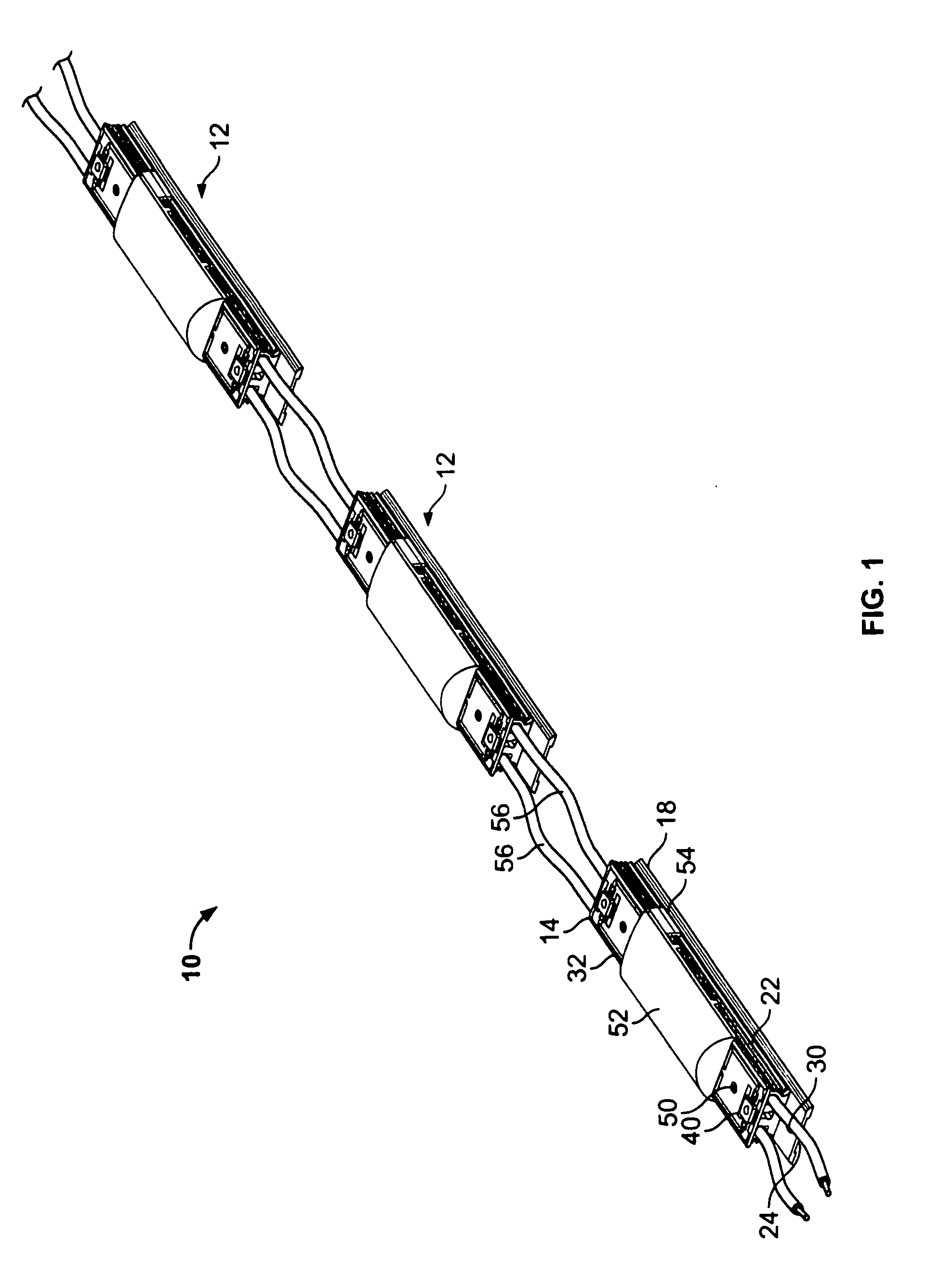
[0044]With reference now to the drawings, and in particular to FIG. 1 thereof, the preferred embodiment of the new and improved illumination system embodying the principles and concepts of the present invention and generally designated by the reference numeral 10 will be described.

[0045]The present invention, the illumination system 10 is comprised of a plurality of components. Such components in their broadest context include a module 12 having a printed circuit board assembly 32, a plurality of electrical components 37, a pair of conductor wires 56 and at least one pair of connectors 60. Such components are individually configured and correlated with respect to each other so as to attain the desired objective.

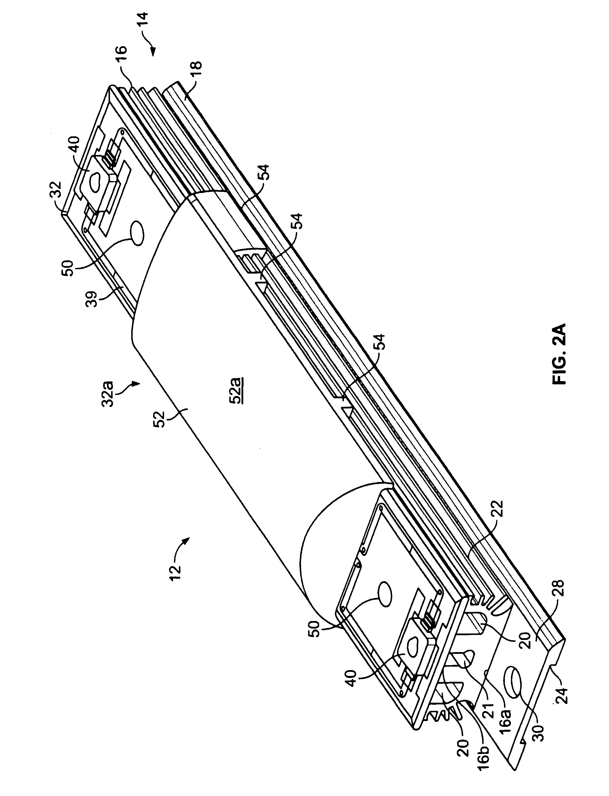
[0046]A plurality of similarly configured modules 12 is first provided. Each module 12 has a metallic heat sink mass 14 with an elongated upper component 16 and an elongated lower component 18. Each upper component 16 includes a generally flat lower surface 16a and upper surf...


PUM


Abstract

A module has a metallic mass with an upper surface having laterally spaced wiring channels and outwardly extending fins. A circuit board is mounted on the module and fabricated of an insulating bottom layer with trace patterns thereon. A plurality of electrical components, including at least one light emitting diode, are coupled to the trace patterns of the circuit board. A pair of continuous conductor wires couple the electrical components with each wire and extend through the wiring channels of the module. At least one pair of connectors extend through the circuit board with upper ends coupled with the trace patterns and lower ends extending downwardly to electrically couple with the wires.

Description

BACKGROUND OF THE INVENTION[0001]1. Field of the Invention[0002]The present invention relates to an illumination system and more particularly to providing high-power, high-intensity light emitting diode modules that are economic to produce and operate.[0003]2. Description of the Prior Art[0004]Recent improvements in the growth and manufacture of the crystals utilized in the production of the light emitting diodes has permitted greater utility and flexibility for its use as an alternative to standard sign industry lighting sources such as neon, fluorescent, cold cathode, metal halide, incandescent and high pressure sodium light sources. Light emitting diodes offer a low voltage alternative to the standard or high voltage lighting sources mentioned. Further developments in light emitting diodes technology have permitted a greater ability to modulate the intensity and light output expanding the potential applications for light emitting diodes lighting technology. Various industries, in...

Claims


Application Information

Patent Timeline
Patent Type & Authority Patents(United States)
IPC IPC(8): F21S4/00
CPCF21S4/001F21V15/01F21V29/75H05K3/28F21V21/002F21V29/004F21Y2101/02H05K1/0203H05K1/056H05K2201/0175H05K2201/10106Y10S362/80H05K1/053F21V29/74F21S4/10F21Y2115/10
Inventor THOMAS, JAMES G.WARNER, BRYAN T.MCCARTHY, MICHAEL J.
Owner ELECTRALED
Why Eureka
Try Eureka