Braided spar for a rotor blade and method of manufacture thereof

a technology of rotor blades and spars, which is applied in the field of composite spars, can solve the problems of reducing affecting the use of rotor blades, and high materials and associated fabrication methods, and achieves the effects of reducing material storage and handling, reducing the complication of delamination, and increasing the ballistic tolerance of spars

Active Publication Date: 2007-01-23
SIKORSKY AIRCRAFT CORP
View PDF16 Cites 56 Cited by
  • Summary
  • Abstract
  • Description
  • Claims
  • Application Information

AI Technical Summary

Benefits of technology

[0010]The rotor blade spar according to the present invention includes a multiple of individual fibers braided together to form a braided sleeve of composite materials. The braided sleeve is a tri-axle braid in which braided bias angled fibers are located at an angle relative the longitudinal axis of the spar. Zero degree fibers are located parallel to the axis and are positioned to be on the upper and lower surfaces of the spar. The braided bias angled fibers are braided around the zero degree fibers. The zero degree fibers are interwoven during the braiding cycle which increases the ballistic tolerance of the spar as delamination is minimized through interaction of the braided geometry. The braided sleeve defines a race-track shaped elongated cross-sectional profile, an elliptical-shaped elongated cross-sectional profile, or an airfoil-shaped elongated cross-sectional profile.
[0011]In a method of manufacture of the braided spar, the braided sleeve is formed dry by a multi-axial braiding machine. The multi-axial braiding machine includes a multiple of spools arranged about an outer ring which rotates about an axis of rotation. Rotation of the outer ring relative the inner ring braids a multiple of individual fibers from the multiple of spools to form the braided sleeve over a mandrel which is passed through the inner ring. Once the braided sleeve is formed upon the mandrel, the mandrel is located within a matched metal mold and resin impregnated. As the braided sleeve is formed with dry filaments, the braiding cycle need not be related to impregnating resin processing. Material storage and handling is reduced in complication which reduces labor intensive process steps and expense. Once the impregnating resin has cured such as through application of thermal energy, the cured braided sleeve and mandrel are removed from the matched metal mold and the mandrel is removed from the finished braided spar.
[0012]The present invention therefore provides a structurally efficient composite spar which locates the fibers in a particular orientation, minimizes weight, and increases damage tolerance. Furthermore, the present invention provides an inexpensive manufacturing process which reduces labor intensive process steps, permits ease of material handling, yet maintains exacting quality standards during assembly.

Problems solved by technology

Despite the inherent weight and strength advantages, widespread use thereof has been impeded by the high cost of materials and associated fabrication methods.
Although effective, these processes are relatively time and labor intensive.
Moreover, prepreg sheets are relatively expensive and require meticulous storage and handling processes which further increase manufacturing expense.
One disadvantage to filament winding relates to difficulties associated with expanding the fibers against the matched metal mold.
As the fibers are initially wound laterally about the mandrel under tension, pressurization sufficient to achieve proper laminate compaction is difficult to achieve.
Should the fibers resist complete and uniform compaction, the composite article may become resin-rich or resin-starved in particular areas resulting in poor laminate quality.
In the case of an elliptically shaped composite article, the conic regions, i.e., the leading and trailing edges, may be vulnerable to unacceptable variations in fiber volume.
Another disadvantage to conventional filament winding relates to the difficulty associated with establishing fiber orientations at or near 0 degrees relative to the longitudinal axis of the mandrel assembly.
Insofar as conventional filament winding apparatus are deficient in this regard, it is common to periodically interrupt the winding operation to interleave unidirectional i.e., 0.degree fibers.
Such interleaving operations are laboriously performed by hand and are relatively time consuming which still further increases manufacturing expense.

Method used


Image

  • Braided spar for a rotor blade and method of manufacture thereof
  • Braided spar for a rotor blade and method of manufacture thereof
  • Braided spar for a rotor blade and method of manufacture thereof

Examples


Embodiment Construction

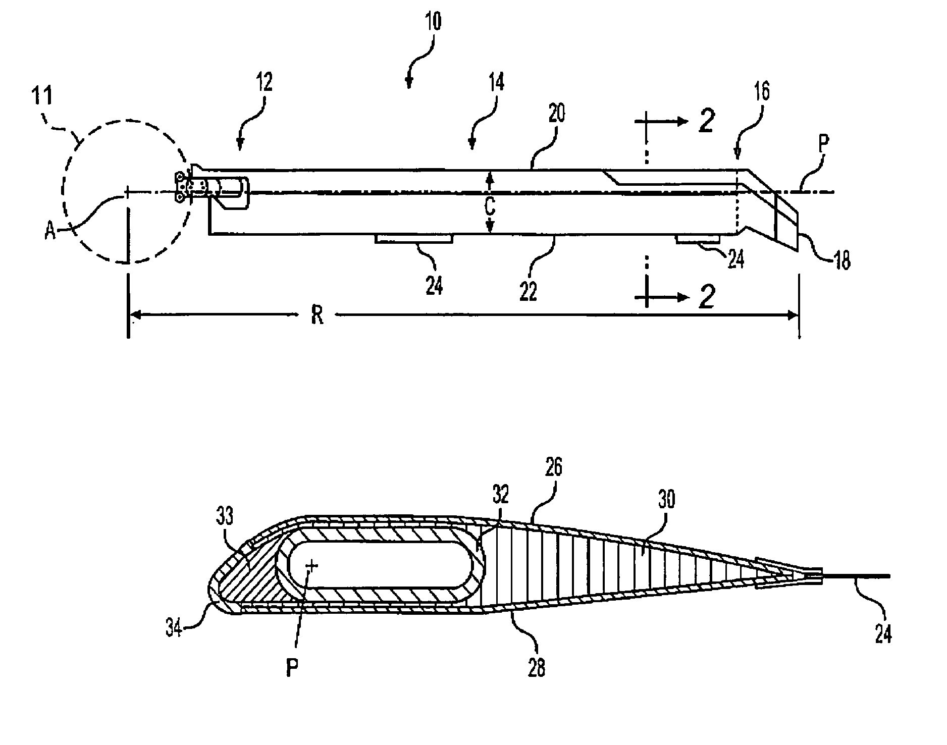
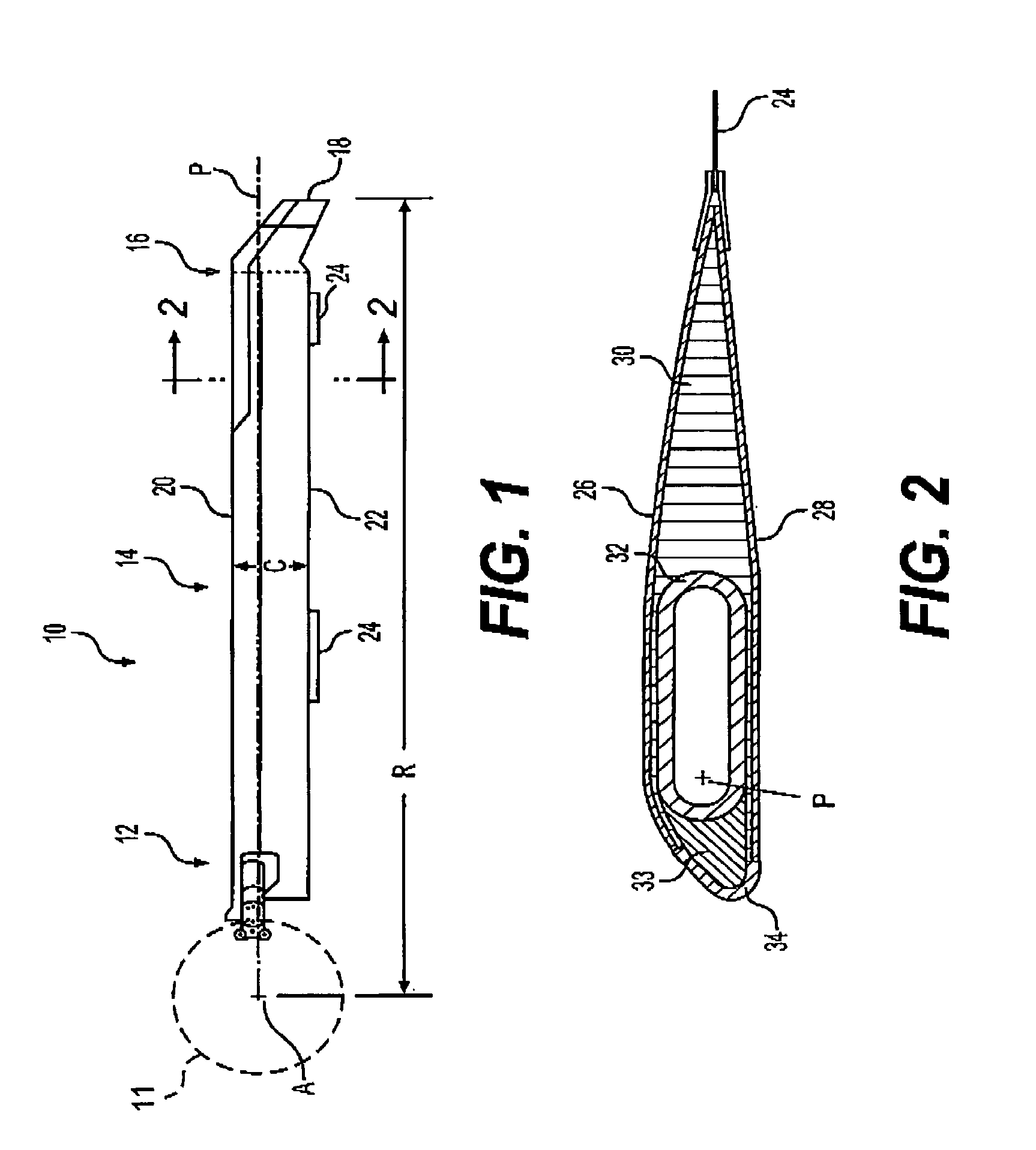
[0022]FIG. 1 schematically illustrates an exemplary main rotor blade assembly 10 mounted to a rotor hub assembly 11 (illustrated schematically) for rotation about an axis of rotation A. The main rotor blade 10 includes an inboard section 12, an intermediate section 14, and an outboard section 16. The inboard, intermediate, and outboard sections 12, 14, 16 define the span of the main rotor blade 10. The blade sections 12, 14, 16 define a blade radius R between the axis of rotation A and a blade tip 18.

[0023]A plurality of main rotor blade assemblies 10 project substantially radially outward from the hub assembly 11 and are supported therefrom in one of numerous attachments. Any number of blades 10 may be used with the rotor system 10. It should be understood that although a rotor system is illustrated in the disclosed embodiment, other applications which will benefit from a hollow composite member such as flex beams, main rotors, tail rotors, propellers, wing spars, turbines, windmil...


PUM

PropertyMeasurementUnit
angleaaaaaaaaaa
bias angleaaaaaaaaaa

Abstract

A braided rotor blade spar includes a tri-axle braid in which braided bias angled fibers are located non-parallel to a longitudinal axis of the spar. Zero degree fibers are located parallel to the axis and are positioned to be on the upper and lower surfaces of the spar. The bias angle fibers are braided around the zero degree fibers. In a method of manufacture of the braided spar, a braided sleeve is formed dry over a mandrel by a multi-axial braiding machine. Once the braided sleeve is formed upon the mandrel, the mandrel is located within a matched metal mold, resin impregnated, and cured. The mandrel is then removed from the finished braided spar.

Description

BACKGROUND OF THE INVENTION[0001]The present invention relates to a hollow composite member, and more particularly to a composite spar which utilizes braided fibers at specific angle orientation and a method for facilitating the manufacture thereof.[0002]A rotor blade spar is a primary structural element of a helicopter rotor blade assembly inasmuch as its primary function is to transfer combined flapwise, edgewise, torsional and centrifugal loads to / from a central torque drive hub member. Typically, a leading edge and trailing edge assembly envelop the spar to yield a desired airfoil contour. The spar typically extends along the length of the rotor blade and mounts at its inboard end to a cuff assembly that facilitates mounting to the hub member.[0003]Fiber reinforced resin matrix composite materials are employed due to their advantageous strength to weight ratio. Despite the inherent weight and strength advantages, widespread use thereof has been impeded by the high cost of materi...

Claims


Application Information

Patent Timeline
Patent Type & Authority Patents(United States)
IPC IPC(8): B64C11/26B29C70/22B29C70/48B64C27/00B64C27/46B64C27/473D04H3/07
CPCB29C70/222B29C70/48D04H3/07B64C27/463B64C27/473B64C27/008B29L2031/082B64C2027/4736D04C1/02D10B2505/02D10B2403/02411
Inventor KOVALSKY, DAVID A.VIOLA, KEVIN
Owner SIKORSKY AIRCRAFT CORP
Why Eureka
Try Eureka