Vaporization source with baffle

a vaporization source and baffle technology, applied in vacuum evaporation coating, sublimation, separation processes, etc., can solve the problems of increasing the intensity of emitted light, low deposition rate on the substrate, and insufficient oled devices, so as to reduce material degradation, increase the uniformity of vaporized organic materials, and reduce the condensation of organic vapors on the side walls of the apparatus.

Active Publication Date: 2007-01-23
GLOBAL OLED TECH
View PDF25 Cites 2 Cited by
  • Summary
  • Abstract
  • Description
  • Claims
  • Application Information

AI Technical Summary

Benefits of technology

[0015]It is an advantage of the present invention that it increases the uniformity of vaporized organic material released by the source. It is a further advantage that only a portion of organic material is exposed to vaporization temperatures at a given time, thereby reducing material degradation. It is a further advantage that the charge of organic material is more evenly vaporized. It is a further advantage that condensation of organic vapors on the side walls of the apparatus is greatly reduced. It is a further advantage of this invention that a series of apertures can be used for release of the organic material vapors without the necessity of heating the apertures directly, thus simplifying construction and permitting more materials and more sealing methods to be used in construction of the device. It is a further advantage of this invention that it can be used for a single use vaporization source.
that it increases the uniformity of vaporized organic material released by the source. It is a further advantage that only a portion of organic material is exposed to vaporization temperatures at a given time, thereby reducing material degradation. It is a further advantage that the charge of organic material is more evenly vaporized. It is a further advantage that condensation of organic vapors on the side walls of the apparatus is greatly reduced. It is a further advantage of this invention that a series of apertures can be used for release of the organic material vapors without the necessity of heating the apertures directly, thus simplifying construction and permitting more materials and more sealing methods to be used in construction of the device. It is a further advantage of this invention that it can be used for a single use vaporization source.

Problems solved by technology

This has been adequate for early OLED devices but is not adequate for OLED devices that rely on the organic layer stack thickness to act as a resonance cavity and thereby increase the intensity of the emitted light.
This strategy requires large deposition chambers, results in very low deposition rates on the substrate and wastes the vast majority of sublimated organic material.

Method used


Image

  • Vaporization source with baffle
  • Vaporization source with baffle
  • Vaporization source with baffle

Examples


Embodiment Construction

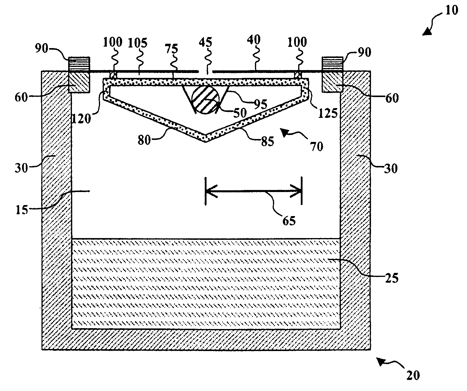
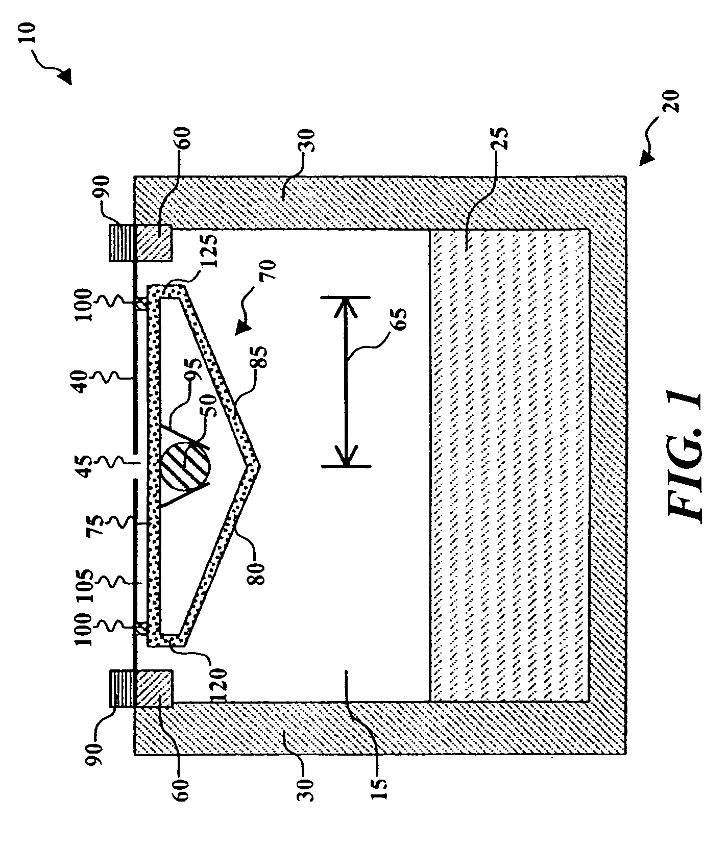
[0018]Turning now to FIG. 1, there is shown a cross sectional view of a vapor deposition source for depositing organic material in accordance with this invention. Vapor deposition source 10 includes a boat 20, which is so constructed with a cavity 15 for holding a charge of organic material 25 and can be sealed as will be seen. Organic material 25 provided in cavity 15 is commonly material that is solid at room temperature and will be further detailed below. A top portion 60 can be attached to boat 20 by various ways, or can be an integral part of boat 20, e.g., by being cast or molded as a single structure.

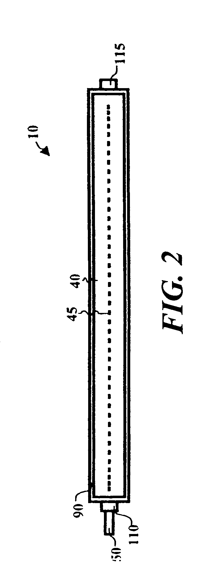
[0019]Vapor deposition source 10 includes an aperture plate 40 that has a plurality of spaced apertures 45. Aperture plate 40 is designed to emulate boat 20 so as to make a leak free seal. Various ways of making airtight seals can be used. For example, clamping means 90 can hold aperture plate 40 in place via the use of bolts to top portion 60. A gasket, for example made out of g...


PUM

PropertyMeasurementUnit
lengthaaaaaaaaaa
widthaaaaaaaaaa
conductanceaaaaaaaaaa

Abstract

A vapor deposition source for depositing organic material includes a boat having a cavity for holding organic material and an aperture plate, having a plurality of spaced apertures, for enclosing the boat. The vapor deposition source also includes a heating element provided in the cavity between the aperture plate and the organic material, and a baffle member in contact with the heating element and having at least three surfaces which absorb energy from the heating element, the first surface redirecting energy to the aperture plate and the second and third surfaces redirecting energy to the boat walls and the organic material.

Description

CROSS REFERENCE TO RELATED APPLICATIONS[0001]Reference is made to commonly assigned U.S. patent application Ser. No. 10 / 971,698 filed Oct. 25, 2004, by Dennis R. Freeman, et al., entitled “Elongated Thermal Physical Vapor Deposition Source With Plural Apertures” (a continuation-in-part of U.S. patent application Ser. No. 10 / 093,739 filed Mar. 8, 2002, now abandoned); commonly assigned U.S. patent application Ser. No. 10 / 352,558 filed Jan. 28, 2003, by Jeremy M. Grace, et al., entitled “Method of Designing a Thermal Physical Vapor Deposition System”; and commonly assigned U.S. patent application Ser. No. 11 / 032,982 filed concurrently herewith, by Dennis R. Freeman, et al., entitled “Customized One Time Vapor Deposition Source”, the disclosures of which are herein incorporated by reference.FIELD OF THE INVENTION[0002]The present invention relates to the field of physical vapor deposition where a source material is heated to a temperature so as to cause vaporization and produce a vapor...

Claims


Application Information

Patent Timeline
Patent Type & Authority Patents(United States)
IPC IPC(8): C23C14/24
CPCC23C14/243C23C14/12C23C14/24
Inventor FREEMAN, DENNIS R.REDDEN, NEIL P.
Owner GLOBAL OLED TECH
Why Eureka
Try Eureka