Objective optical system employing grin lens

a technology of objective lenses and optical systems, applied in the field of objective optical systems employing gradient index lenses, can solve the problems of increasing the weight and size of objective optical systems, unable to meet the requirements of ultra-thin optical pickups, and the second method is limited in correcting the coma aberration generated in objective lenses, so as to achieve the effect of removing coma aberration and chromatic aberration, and ultra-small optical systems

Active Publication Date: 2007-01-23
SAMSUNG ELECTRONICS CO LTD
View PDF10 Cites 24 Cited by
  • Summary
  • Abstract
  • Description
  • Claims
  • Application Information

AI Technical Summary

Benefits of technology

[0011]An apparatus consistent with present invention provides an objective optical system employing an ultra-thin gradient

Problems solved by technology

However, this method increases the weight and size of objective optical systems, and accordingly, is not suitable for ultra-thin optical pickups.
Therefore, the second method is limited in correcting coma aberration generated in objective lenses with a high NA in ultra-small optical pickups.
However, with this method, it is not easy to form a fine pitch when manufacturing the diffractive optical lens DOE and to obtain sufficient transmittance.
In particular, for a doublet hybrid lens, it is difficult

Method used


Image

  • Objective optical system employing grin lens
  • Objective optical system employing grin lens
  • Objective optical system employing grin lens

Examples


first embodiment

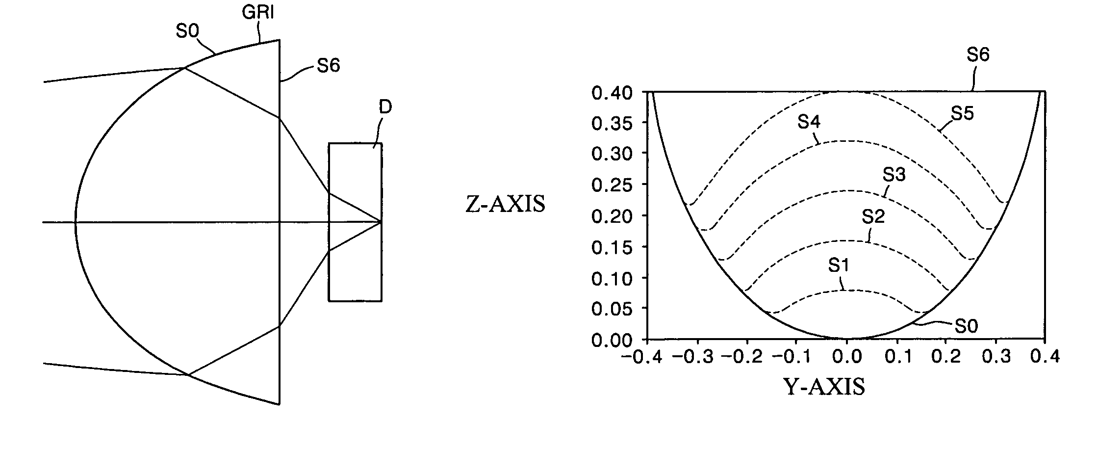
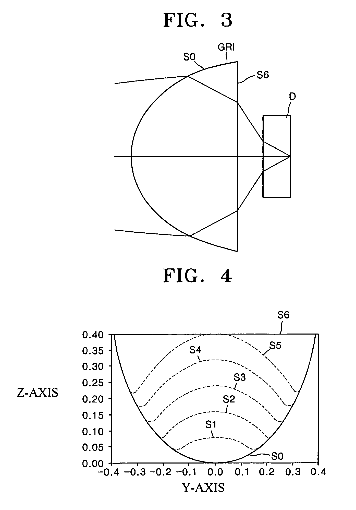
[0037]FIG. 3 is a schematic sectional view of an objective optical system according to the present invention. Referring to FIG. 3, the objective optical system employs a convex-plano gradient index (GRIN) lens GR1 as an objective lens. The GRIN lens GR1 forms a light spot having a desired size by focusing light on an optical disk D. The refractive index n of the GRIN lens GR1 may be changed as shown in Equations 4, 5 and 6. Equation 4 is equivalent to Equation 1, Equation 5 is equivalent to Equation 2 and Equation 6 is equivalent to Equation 3. A range of the refractive index n varies according to media from which the GRIN lens GR1 is made. It is preferable that the refractive index n is set in a range of a tolerance less than ±10%.

n(r, z)=n0+nr2r2+nr4r4+ . . . +nz1z+nz2z2+  [Equation 4]

n(z)=n0+n1z+n2z2+n3z3+n4z4+  [Equation 5]

n(r)=n0n2r2+n4r4+  [Equation 6]

[0038]In Equation 1 through Equation 6, z represents a distance from the center of the lens in an axial direction, and r repres...

second embodiment

[0044]FIG. 5 is a schematic sectional view illustrating a configuration of an objective optical system according to the present invention. Referring to FIG. 5, the objective optical system comprises a GRIN sheet lens GR2 having a refractive index n satisfying one of Equation 1 through Equation 3 (Equation 4 through Equation 6) and a plano-convex diffractive lens PCD having a planar incident surface sp and a convex emissive surface sd disposed in an optical path of light emitted from the GRIN lens GR2.

[0045]Since the emissive surface sd of the plano-convex diffractive lens PCD is a diffractive surface, the plano-convex diffractive lens PCD separates light refracted by the GRIN lens GR2 into a plurality of diffracted light beams including a zero-order light beam, a +1-order light beam, and −1-order light beam. Here, the plano-convex diffractive lens PCD may directly contact an emissive surface of the GRIN lens GR2 or may be spaced apart from the emissive surface of the GRIN lens GR2 b...

third embodiment

[0048]FIG. 7 is a schematic sectional view of an objective optical system according to the present invention. Referring to FIG. 7, the objective optical system includes a convex-plano refractive lens CPR having a convex aspherical incident surface si and a planar emissive surface so and a GRIN lens GR2 whose refractive index n(z) is changed in an axial direction according to Equation 2 which is equal to Equation 5. For example, when the convex-plano refractive lens CPR has a thickness of 0.4470 mm and an etching depth z of 0.272 mm from the aspherical surface, a clear aperture may be 2×0.418. The GRIN lens GR2 has a thickness of 0.1806 mm and a working distance between an optical disk D and the GR2 is 0.1 mm.

[0049]Table 1 shows the simulation results when using laser diodes emitting blue light beams of wavelengths 400 nm, 405 nm, and 410 nm to condense light using the objective optical system shown in FIG. 7, simulation results are shown in Table 1.

[0050]

TABLE 1Wavefront error (on / o...


PUM


Abstract

Provided is an objective optical system employing a gradient index (GRIN) lens. A refractive index of the GRIN lens is changed in an axial direction and a direction perpendicular to the axial direction. The GRIN lens has a refractive index n satisfying the following equation:
n(r,z)=i=0nr2ir2i+j=0nzjzj
where z is a distance from the center of the lens in the axial direction and r is a distance from the center of the lens in the direction perpendicular to the axial direction. Thus, an objective optical system with a high numerical aperture can correct aberration.

Description

[0001]This application claims the priority of Korean Patent Application No. 2003-40084, filed on Jun. 20, 2003, in the Korean Intellectual Property Office, the disclosure of which is incorporated herein in its entirety by reference.BACKGROUND OF THE INVENTION[0002]1. Field of the Invention[0003]An apparatus consistent with the present invention relates to an objective optical system employing a gradient index (GRIN) lens and, more particularly, to an objective optical system employing a GRIN lens that can correct aberrations and can be used in an ultra-small optical pickup.[0004]2. Description of the Related Art[0005]Objective lenses are the main parts used in optical disk drives (ODDs), such as compact disks (CDs) or digital versatile disks (DVDs), to record or reproduce information. Objective lenses condense laser beams emitted from laser diodes, which are light sources, and focus the laser beams on recording surfaces of optical disks to record information. Objective lenses may al...

Claims


Application Information

Patent Timeline
IPC IPC(8): G02B3/00G02B13/18G02B3/02G02B9/00G02B13/00G11B7/135
CPCG02B3/0087G02B13/0055G11B7/13922G11B7/1374G11B7/1353G02B13/00
Inventor JUNG, MEE-SUKLEE, MYUNG-BOKCHO, EUN-HYOUNGKIM, HAE-SUNGSOHN, JIN-SEUNG
Owner SAMSUNG ELECTRONICS CO LTD
Why Eureka
Try Eureka