Cascade control system for network units

a control system and network unit technology, applied in the field of communication networks, can solve problems such as the removal of a link between units

Active Publication Date: 2007-01-23
VALTRUS INNOVATIONS LTD
View PDF42 Cites 22 Cited by
  • Summary
  • Abstract
  • Description
  • Claims
  • Application Information

AI Technical Summary

Benefits of technology

[0009]One object of the present invention is to provide an improved and versatile control path by means of which...

Problems solved by technology

Such an ‘operational failure’ may be either the removal or powering-down, for whatever reason, of a unit...

Method used


Image

  • Cascade control system for network units
  • Cascade control system for network units
  • Cascade control system for network units

Examples


Embodiment Construction

(a) General Description of a Switch

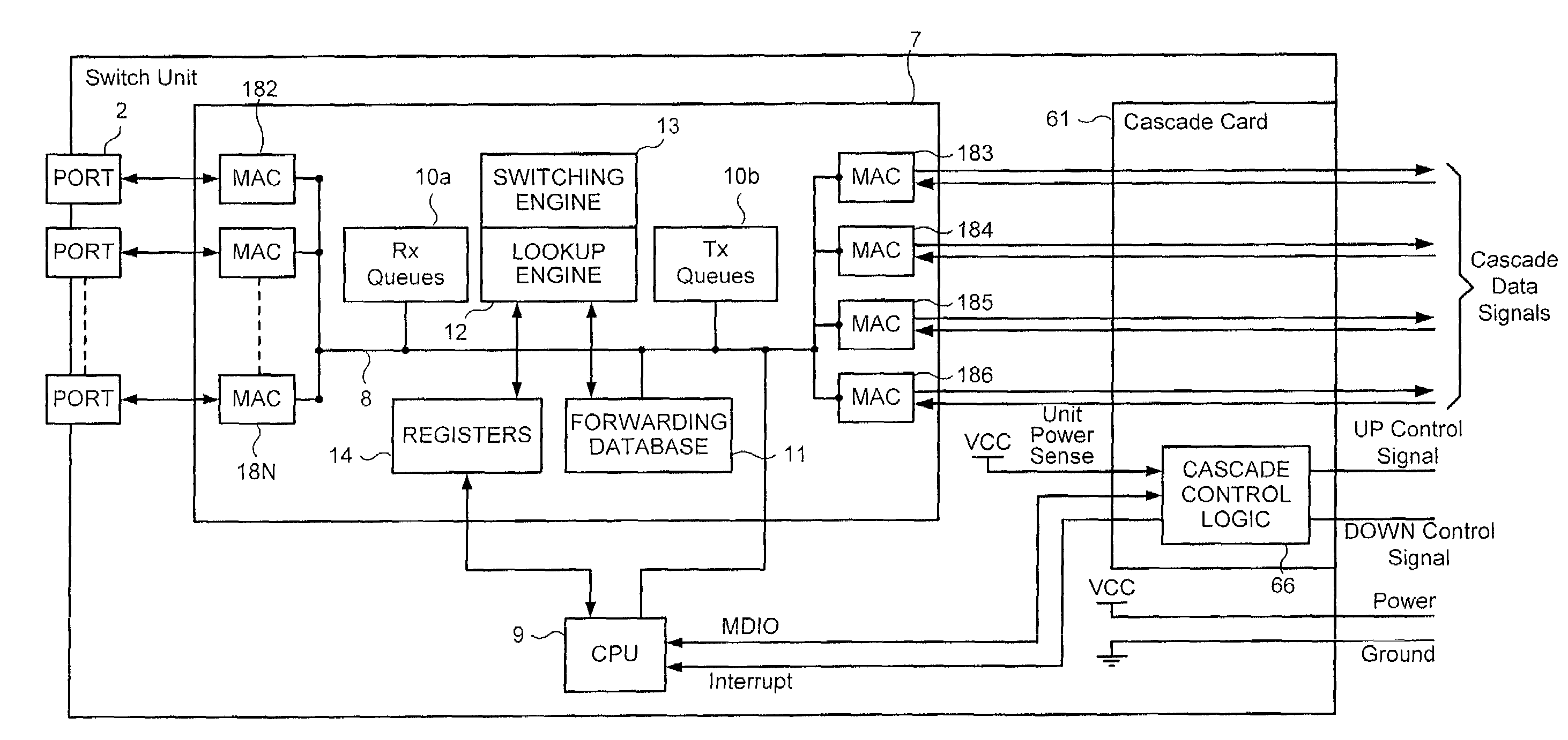
[0038]The reader is presumed to be generally familiar with the design construction and operation of network switches and routers intended for the handling and processing of address data packets, particularly according to Ethernet formats and protocols and procedures in accordance, for example, with IEEE Standard 802.3 dated December 1998. However, for the sake of completeness, a brief and deliberately simplified review of a network switch is given hereinafter for the sake of convenience. A more detailed description of the features of the switch relevant to the present invention will be given with reference to FIG. 18.

[0039]The switch 1 shown in FIG. 1 comprises a multiplicity of ordinary or ‘front panel’ ports represented in the Figure by ports 2 to N. Very typically there would be twelve or perhaps twenty-four of these front panel ports, which are selectively connected to other devices such as hubs, switches, user terminals and suchlike typical of...


PUM


Abstract

Cascade control logic for use in a switch or other network unit that can be used in a cascaded stack can maintain normally a point-to-point half-duplex connection for control data with each of the next preceding and next succeeding units in the cascade. Each cascade logic device is organised so that for one direction, conveniently called the up direction, a device is a master and in the other direction the device is a slave in respect of the control path. A control device will generate master control frames in the up direction and deliver slave control frames in the down direction. The control device is organised so that in the absence of reception of valid control frames on a control link control data which would otherwise be sent out on that link is looped back within the control device. In this manner the control device can maintain under normal circumstances two virtual control channels which can ‘self-heal’ notwithstanding the failure or powering-down of a unit in the cascade.
Status information represented by the control frames can be used to control a switching engine to provide self healing of the data path in the cascade.

Description

CROSS-REFERENCE TO RELATED APPLICATION[0001]Donoghue et al., entitiled ‘Cascade system for network units’ filed on the same day as the present application and commonly assigned herewith.FIELD OF THE INVENTION [0002]This invention relates to communication networks. More particularly the invention relates to networks compatible with ‘Ethernet’ transmission formats and protocols. The invention specifically concerns what is known as the ‘cascading’ of switches or other units in or for such a network.BACKGROUND TO THE INVENTION [0003]The physical elements in a packet-based data communication system commonly include multi-port units such as switches and routers. Such units are commonly and conveniently manufactured with a fixed plurality of ports by means of which the units can be connected by way of appropriate transmission links (such as cables or optical fibres) to other units or user terminals. In order to provide greater versatility in constructing networks while minimising the numbe...

Claims


Application Information

Patent Timeline
IPC IPC(8): H04L12/28H04J3/00H04L12/56H04L12/433
CPCH04L12/433
Inventor DONOGHUE, BRYAN JO'NEILL, EUGENEO'MALLEY, EDELEMORAN, PAUL JCHOI, KAMNOLAN, JEROME
Owner VALTRUS INNOVATIONS LTD
Why Eureka
Try Eureka