

Image processing method for generating three-dimensional images on a two-dimensional screen
- Summary
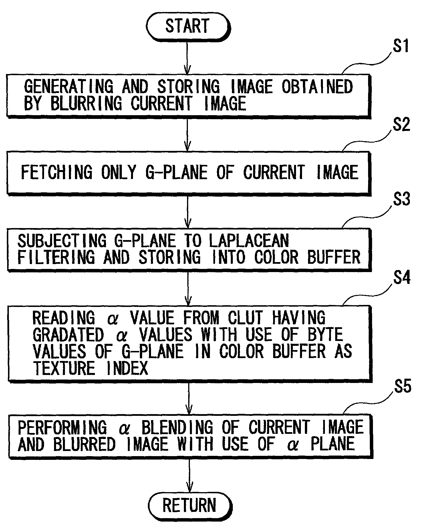
- Abstract
- Description
- Claims
- Application Information
AI Technical Summary
Benefits of technology
Problems solved by technology
Method used
Image

Examples
Embodiment Construction
Constitution of an Image Processing Device of the Present Embodiment
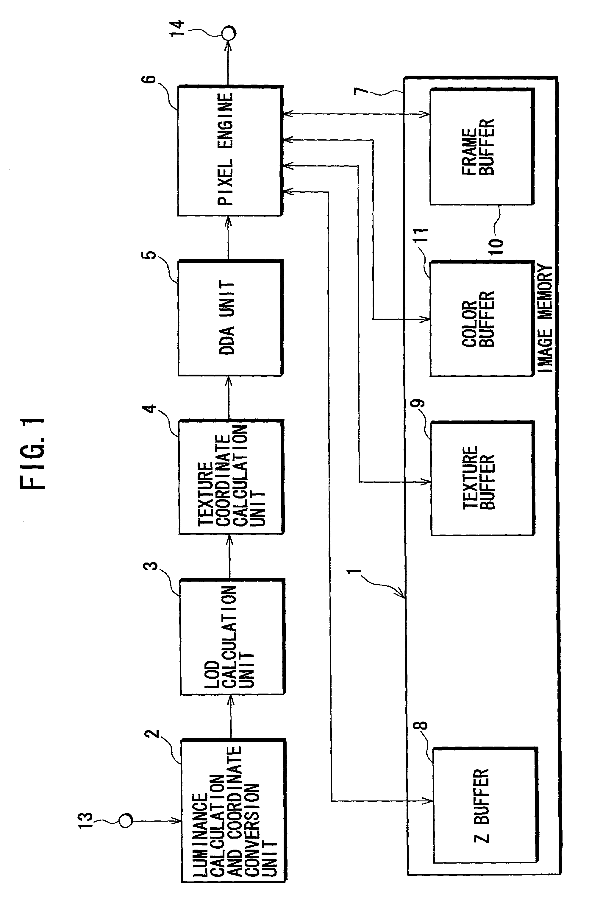
[0026]FIG. 1 shows a schematic configuration of a principal portion of an image processing device 1 according to the embodiment of the present invention. The image processing device 1 of the embodiment is a device for generating a two-dimensional image based on texture mapping onto three-dimensional polygons, and is applicable to television game machines, personal computers and three-dimensional graphic devices (in particular, to so-called graphic synthesizers).
[0027]The image processing device 1 shown in FIG. 1 mainly comprises a luminance calculation and coordinate conversion unit 2, an LOD (Level Of Detail) calculation unit 3, a texture coordinate calculation unit 4, a DDA (Digital Differential Analyzer) unit 5, a pixel engine 6 and an image memory 7.
[0028]The image memory 7 further comprises various storage areas such as a Z buffer 8 for storing values in the depth-wise direction from a viewpoint (Z coordinate v...
PUM
 Abstract
Description
Claims
Application Information