
Apparatus and method for controlling regenerative braking of an electric vehicle

a technology of electric vehicles and regenerative braking, which is applied in the direction of braking components, gas pressure propulsion mountings, driver interactions, etc., can solve the problems of insufficient regenerative braking, negatively affecting the vehicle's dynamic control, and driver confusion, so as to improve the energy reclamation efficiency of regenerative braking and optimize the distribution of braking for

Active Publication Date: 2007-01-23
HYUNDAI MOTOR CO LTD +1
View PDF5 Cites 31 Cited by
  • Summary
  • Abstract
  • Description
  • Claims
  • Application Information

AI Technical Summary

Benefits of technology

The present invention provides a method and apparatus for controlling regenerative braking of an electric vehicle. The invention achieves harmonized braking force with the driver's operation, enhances energy reclamation efficiency of regenerative braking, and optimizes braking force distribution between driven and non-driven wheels. The apparatus includes a brake pedal, hydraulic modules for braking the non-driven wheel, and an electronic control unit for detecting and controlling regenerative braking and hydraulic braking of the driven wheel. The non-driven wheel braking force is calculated based on the brake fluid pressure and the effective radius of the brake disk or wheel cylinder. The target braking force for the driven wheel is calculated based on the normal force applied to the driven wheel under braking. The invention allows for a more efficient use of energy and improved performance of electric vehicles.

Problems solved by technology

Hydraulic brakes are used as regenerative braking is usually insufficient for required deceleration.
Application of braking force only on the driven wheels may negatively impact the vehicle's dynamic control.
Accordingly, a driver may feel confused due to undesired deceleration of the vehicle that has little relationship to brake pedal operation.
Such low control of regenerative braking deteriorates energy reclamation rate thereof.
In addition, according to the prior art, an optimal design for braking force distribution between driven and non-driven wheels was difficult because the regenerative braking force acts only on driven wheels.

Method used


Image

  • Apparatus and method for controlling regenerative braking of an electric vehicle
  • Apparatus and method for controlling regenerative braking of an electric vehicle
  • Apparatus and method for controlling regenerative braking of an electric vehicle

Examples


Embodiment Construction

[0056]An embodiment of the present invention will hereinafter be described in detail with reference to the accompanying drawings.

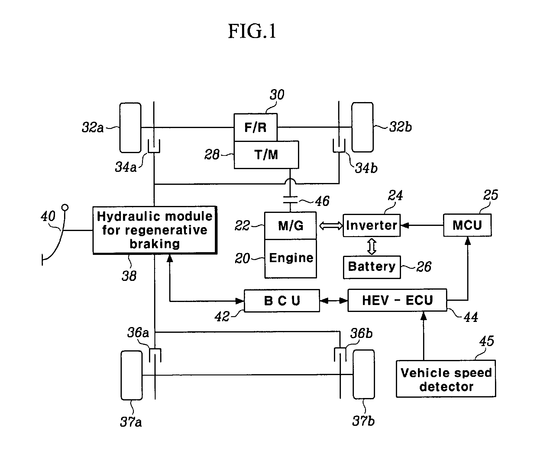
[0057]FIG. 1 is a schematic diagram of an electric vehicle according to an embodiment of the present invention.

[0058]The present invention is applicable not only to a hybrid electric vehicle but also to a pure electric vehicle. However, an embodiment in which the spirit of the present invention thereof is applied to a pure electric vehicle is obvious from an embodiment described hereinafter, in which the spirit of the present invention is applied to a hybrid electric vehicle. Therefore, an embodiment in which the spirit of the present invention is applied to a hybrid electric vehicle is hereinafter described in detail.

[0059]As shown in FIG. 1, a hybrid electric vehicle according to an embodiment of the present invention includes an engine 20 and a motor / generator unit (hereinafter referred to as M / G unit) 22 as its power source.

[0060]In a front-wheel drive...


PUM


Abstract

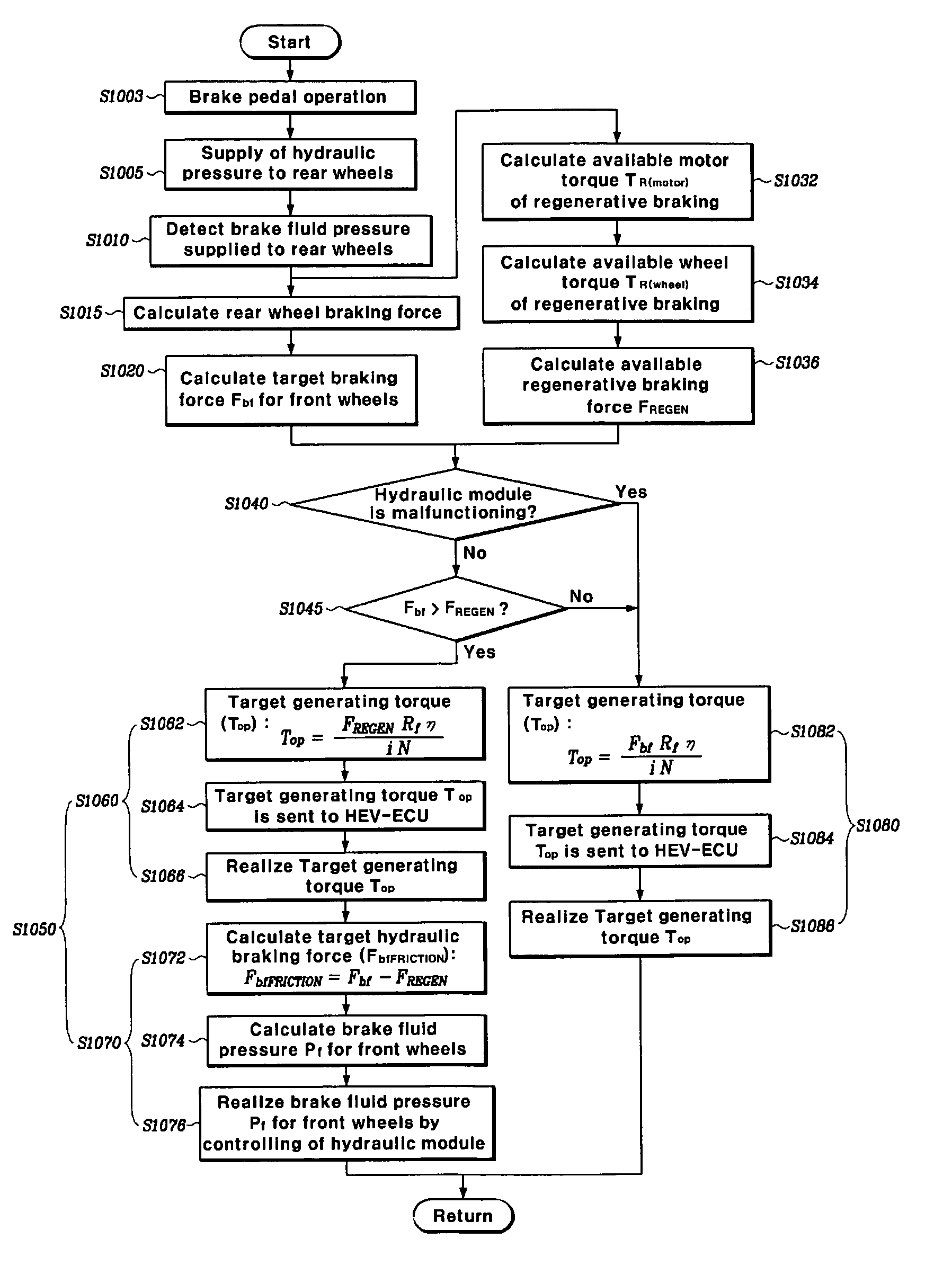
The method includes detecting a brake pedal operation. Thereafter, calculating a non-driven wheel braking force applied to a non-driven wheel of the electric vehicle according to the brake pedal operation. Subsequently, calculating a target braking force for a driven wheel corresponding to the non-driven wheel braking force. Then, calculating an available regenerative braking force for the driven wheel. The method then compares the target braking force and the available regenerative braking force for the driven wheel. The method also controls regenerative braking and hydraulic braking of the driven wheel on the basis of the comparison of the target braking force and the available regenerative braking force for the driven wheel.

Description

CROSS-REFERENCE TO RELATED APPLICATIONS[0001]This application claims priority of Korean Application No. 10,2003-0100907, filed Dec. 30, 2003, the disclosure of which is incorporated herein by reference.FIELD OF THE INVENTION[0002]Generally, the present invention relates to an electric vehicle. More particularly, the present invention relates to a method and apparatus for controlling regenerative braking of an electric vehicle.BACKGROUND OF THE INVENTION[0003]Instead of a conventional internal combustion engine (hereinafter referred to as an engine), an alternative power source is under investigation to be used as a power source of a vehicle in order to reduce environment pollution caused by exhaust gas of the vehicle and to prepare for a shortage of limited petroleum resources.[0004]An electric vehicle is a typical example thereof. An electric vehicle runs a motor using electric energy stored in a battery, and uses a driving force of the motor as an entire or partial power source of...

Claims


Application Information

Patent Timeline
Patent Type & Authority Patents(United States)
IPC IPC(8): B60W20/00B60T8/64G06F7/00B60T8/17B60L7/14B60L7/22B60L7/24B60L7/26B60L50/16B60T1/10B60T8/00B60T8/1766B60T8/26G06F17/00
CPCB60K6/48B60L7/26B60T1/10B60T8/00B60T8/267B60W10/18B60W20/102B60W30/18127Y02T10/92B60T2270/608Y02T10/6221B60T2270/602B60L7/14B60L15/2009B60L15/2054B60L2210/40B60L2240/12B60L2240/421B60L2240/423B60L2240/461B60L2240/463B60L2240/486B60L2250/26B60W2050/0025B60W20/11B60L50/16B60L58/12Y02T10/62Y02T10/64Y02T10/70Y02T10/7072Y02T10/72B60L7/22
Inventor PARK, JIN HOKIM, HYUN SOOYEO, HOON
Owner HYUNDAI MOTOR CO LTD
Learn More