Potato drip irrigation system and method

a drip irrigation and potato technology, applied in the field of plant husbandry, can solve the problems of increasing the potential for disease, reducing the quality of potatoes, and disadvantages of center-pivot irrigation systems, so as to improve the yield of potatoes, improve the growing and yield of potatoes, and reduce excessive wet conditions

Inactive Publication Date: 2007-01-30
ANDERSEN BRIAN L
View PDF0 Cites 4 Cited by
  • Summary
  • Abstract
  • Description
  • Claims
  • Application Information

AI Technical Summary

Benefits of technology

[0013]An arrangement is provided for improving the growing and the yield of potatoes from potato plants.
[0014]According to one aspect, an arrangement is provided for improving the yield of potato crops. The arrangement includes a bed, a plurality of pairs of parallel rows of potato plants, and a drip irrigation tape. The bed is provided for multiple rows of potato plants. The plurality of pairs of parallel rows of potato plants in the bed have an inter-row gap between the rows in each pair of rows spaced from one another sufficiently to provide a moisture permeable agronomic soil corridor between the rows in each pair of rows to provide a supply of water to a root zone of each row within each pair of rows of potato plants while maintaining aerated soil within and above the agronomic soil corridor to reduce excessively wet conditions adjacent the crop canopy and a solar light corridor provided between adjacent pairs of rows to provide increased solar energy to the potato plants. The drip irrigation tape has emitters provided intermediate rows within each pair of parallel rows of potato plants below a soil surface of the bed in the agronomic soil corridor.
[0015]According to another aspect, an arrangement is provided for improving the growing of potato crops. The arrangement includes a bed for multiple rows of potato plants, a plurality of pairs of parallel rows of potato plants, and a line-source irrigation system comprising a drip irrigation tape. Each of the rows of potato plants has a root zone. The plurality of pairs of parallel rows of potato plants in the beds have a gap between adjacent pairs of rows. Placement of the gap, in combination with in-row potato plant spacings, provides for a substantially equidistant, equal-area arrangement of light area for a potato plant. The line-source irrigation system includes a drip irrigation tape, with emitters, provided intermediate to each row with each pair of parallel rows of potato plants. The proximity of the emitters and tape is configured to provide a substantially equal, uniform and optimal supply of water to the root zone of each plant within each row while maintaining aerated soil conditions about the root zone of each plant and mitigating excessively wet conditions within a canopy of the potato plants.

Problems solved by technology

Moreover, the additional handling of potatoes can decrease their quality due to bruising and other factors.
However, there are disadvantages to center-pivot irrigation systems.
One problem is that water is applied from overhead, potentially leading to excessively wet conditions within the crop canopy that tends to increase the potential for disease.
Due to the intensity of the irrigation under a center-pivot irrigation device, there is also a tendency for the impact of water droplets to “beat down” the soil and canopy, which has a negative effect on plant health as well.
Furthermore, there are limits as to how frequent an area within the irrigated field can receive needed moisture as it depends upon the traveling speed of the system.
These factors do provide some challenges to growing an “above average” crop that suits many target markets.
With a conventional hill planting system, there are severe limitations to providing optimal plant spacing.
It follows that the grower is therefore unable to specifically and uniformly define the field area occupied by each plant.
The outer rows 24 and 30 are not optimally irrigated by tape 32 because they are spaced apart from tape 32 an unacceptable distance which means that outer rows are under-watered (or inner rows are over-watered).

Method used


Image

  • Potato drip irrigation system and method
  • Potato drip irrigation system and method
  • Potato drip irrigation system and method

Examples


Embodiment Construction

[0026]This disclosure of the invention is submitted in furtherance of the constitutional purposes of the U.S. Patent Laws “to promote the progress of science and useful arts” (Article 1, Section 8).

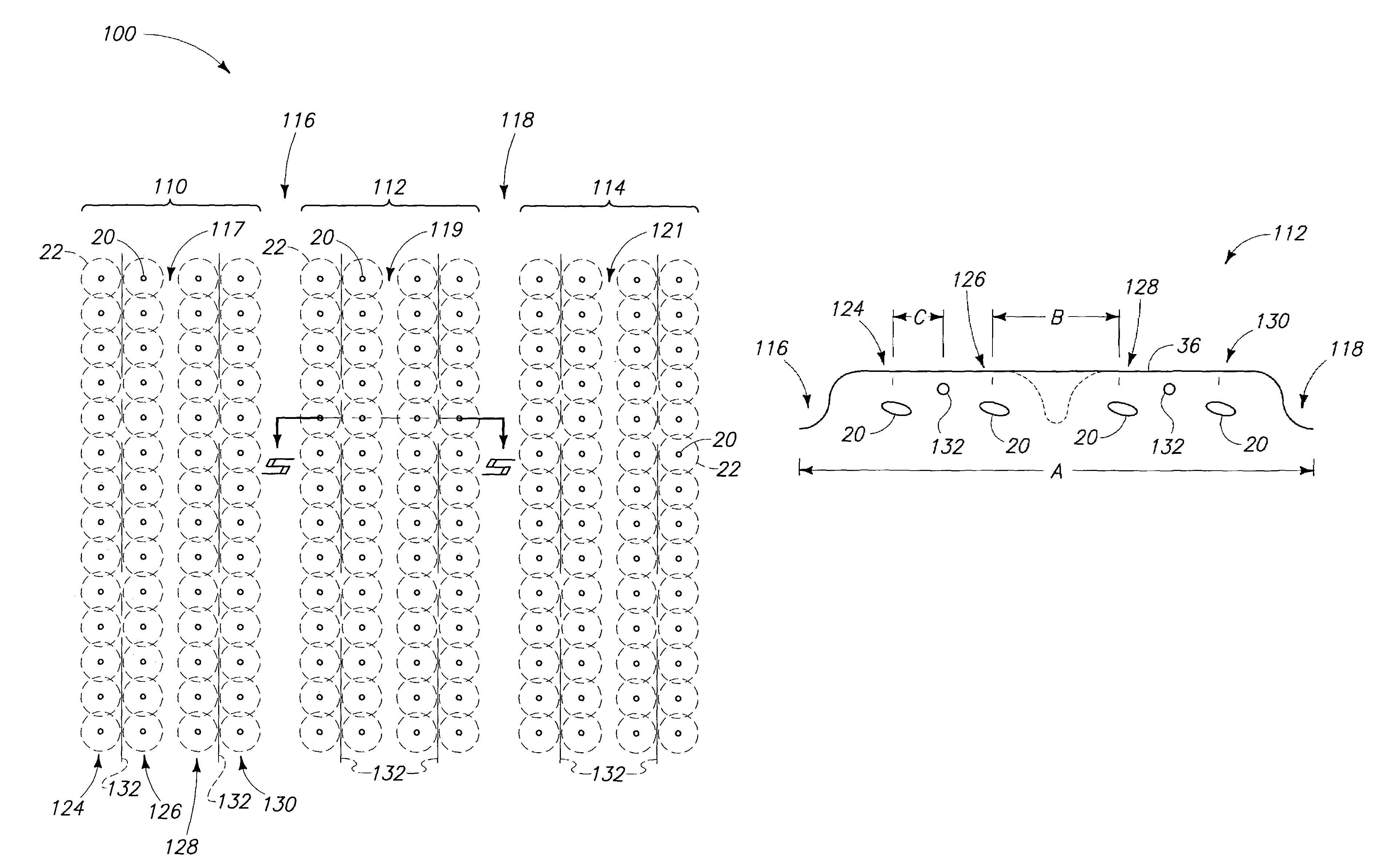
[0027]Reference will now be made to a preferred embodiment of Applicants' invention. An exemplary implementation is described below and depicted with reference to the drawings comprising a system and method (or arrangement) for growing potato crops, as well as improving yield and quality, identified by reference numeral 100. While the invention is described by way of a preferred embodiment, it is understood that the description is not intended to limit the invention to such embodiments, but is intended to cover alternatives, equivalents, and modifications which may be broader than the embodiments, but which are included within the scope of the appended claims.

[0028]In an effort to prevent obscuring the invention at hand, only details germane to implementing the invention will be described...


PUM


Abstract

An arrangement is provided for improving the yield of potato crops. The arrangement includes a bed, a plurality of pairs of parallel rows of potato plants, and a drip irrigation tape. The bed is provided for multiple rows of potato plants. The plurality of pairs of parallel rows of potato plants in the bed have an inter-row gap between the rows in each pair of rows spaced from one another sufficiently to provide a moisture permeable agronomic soil corridor between the rows in each pair of rows to provide a supply of water to a root zone of each row within each pair of rows of potato plants while maintaining aerated soil within and above the agronomic soil corridor to reduce excessively wet conditions adjacent the crop canopy and a solar light corridor provided between adjacent pairs of rows to provide increased solar energy to the potato plants. The drip irrigation tape has emitters provided intermediate rows within each pair of parallel rows of potato plants below a soil surface of the bed in the agronomic soil corridor. A method is also provided.

Description

TECHNICAL FIELD[0001]This invention pertains to plant husbandry. More particularly, the present invention relates to potato plant arrangements and methods of planting potatoes which improves crop yield and quality.BACKGROUND OF THE INVENTION[0002]The production of potatoes forms an important portion of the agriculture economy of the United States. Potatoes are used for both fresh vegetable markets, as well as value-added processed foods. For example, in the United States approximately 1.25 million acres of potatoes are planted each year. This acreage results in a farm-gate value of 3.06 billion dollars, according to the National Agricultural Statistician Service (NASS) of the U.S. Department of Agriculture (USDA), for year 2001. Within Washington State alone, approximately 160,000 acres of potatoes are grown annually for both domestic and international consumption. As in any industry, there exists a desire to increase productivity and efficiency in the process of taking a potato cro...

Claims


Application Information

Patent Timeline
Patent Type & Authority Patents(United States)
IPC IPC(8): A01G1/00A01C23/04A01G25/06
CPCA01G25/06A01C23/042Y02P60/12Y02A40/22
Inventor ANDERSEN, BRIAN L.MITTELSTADT, ROBERTANDERSEN, MICHAELCHRISTENSEN, GARY
Owner ANDERSEN BRIAN L
Why Eureka
Try Eureka