Lightweight helicopter

a light-weight, helicopter technology, applied in the direction of microlight aircraft, hang glider aircraft, propellers, etc., can solve the problems of helicopters that helicopters are expensive to acquire, and helicopters are difficult to learn to operate and fly safely

Inactive Publication Date: 2007-01-30
COUNCIL OF SCI & IND RES
View PDF20 Cites 15 Cited by
  • Summary
  • Abstract
  • Description
  • Claims
  • Application Information

AI Technical Summary

Problems solved by technology

While a number of affordable aircraft, such as micro-lights and powered hang gliders, have brought the possibilities of powered flight within the reach of the public and lead to an upsurge in aerosports, the same is not true of the helicopter.
The helicopter remains an expensive machine to acquire and difficult to learn to operate and to fly safely.
The helicopter requires expensive training in a similar two-seat helicopter, which may require 100 hours and cost $13,700–$18,300 (Rs.
This difference arises mainly due to the increased complexity of a conventional helicopter, which results in an expensive machine that is difficult to learn to fly.
One drawback being that the pilot is freely suspended in a prone position (i.e, face downward) under the downwash of the rotors, which is likely to lead to large swaying and buffeting of the pilot making it difficult to control the aircraft.
In another drawback, the prone position is also considered to be extremely dangerous from a crash-worthiness point of view.
In an additional drawback, the absence of a positive control in the yaw direction in hover and low forward speeds could lead to undesirable spinning of the pilot about a vertical axis.
It appears very difficult to introduce any further controls to overcome this problem, since both the hands of the pilot are fully occupied in manipulating the control bar, the rotor blade pitch control and the engine throttle and the pilots' feet are not available to carry out any control function because of the prone freely hanging position.
However, due to the lower rotor being placed in the wake of the upper rotor, there is an interference effect, which results in an increase in the power required for a given thrust, thus nullifying to some extent, the savings in power of the tail rotor.
With all these features, the mechanical complexity is very high, leading to an expensive and complex machine.
Thus, the HT-1 (1) could achieve the ultra-light category but it may be somewhat underpowered and the HT-1 (2) could have sufficient power but would not meet the ultra-light category weight limit.

Method used


Image

  • Lightweight helicopter
  • Lightweight helicopter
  • Lightweight helicopter

Examples


Embodiment Construction

[0022]The following description of the various embodiments is merely exemplary in nature and is in no way intended to limit the invention, its application or uses.

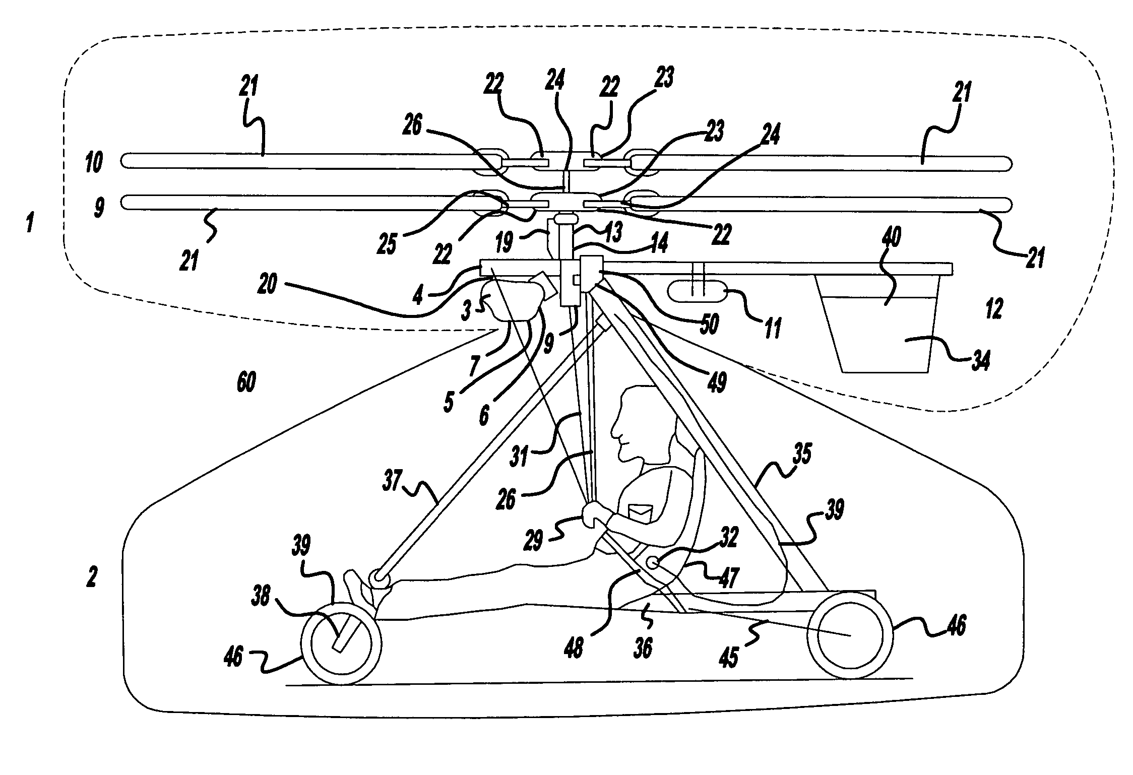
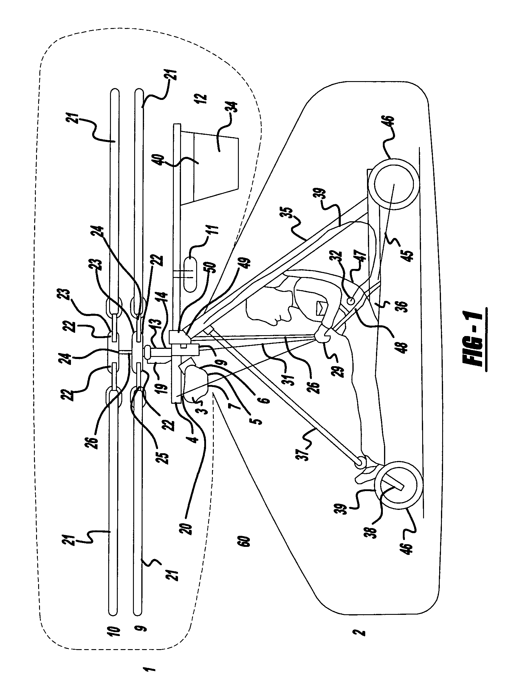
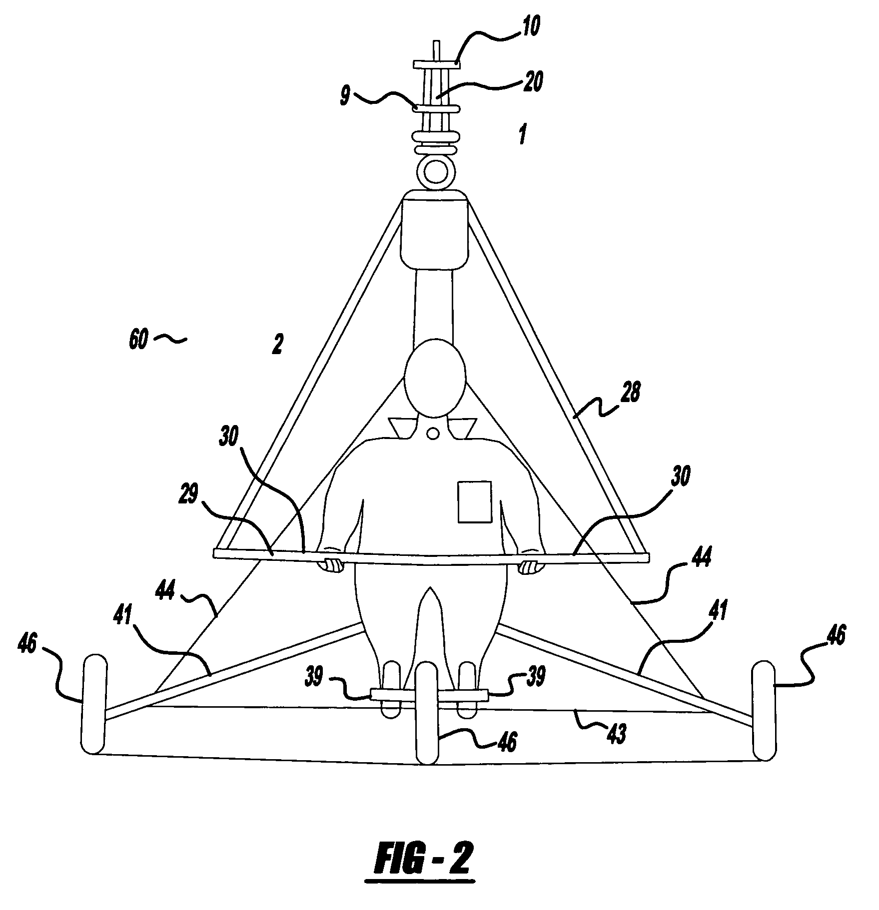
[0023]The helicopter of the present invention, as shown in FIGS. 1 and 2, comprises a rotary wing assembly 1 and a tricycle assembly 2. The rotary wing assembly 1 comprises an engine 3 with a primary gearbox 4 connected through a flexible coupling 5 and a sprag clutch 6 to a secondary gearbox 7.

[0024]The secondary gearbox 7 and the engine 3 are mounted below a keel post 8 through flexible mounts 20. The secondary gearbox 7 drives two contra-rotating rotors 9, 10. The keel post 8 also carries a fuel tank 11 and an articulated tail 12. The secondary gearbox 7, as detailed in FIG. 3, houses a pair of concentric shafts 13, 14 connected to bevel gears 15, 16. These bevel gears engage the pinion gear 17, connected through a freewheeling clutch 18 to the engine 3 through the sprag clutch 6 and the flexible coupling 5.

[0025]The ro...


PUM


Abstract

The present invention relates to a lightweight helicopter with features of coaxial, contra-rotating rotors and weight shift control. It has a rotary wing unit attached to a tricycle assembly through a hang bolt. The rotary wing unit has an engine mounted below a keel post, which drives a pair of contra-rotating coaxial rotors through a primary gearbox and a secondary gear box. The keel post is attached to a triangular control frame, the base of which forms the control bar. The keel post also supports a fuel tank connected to the engine and a tail plane having one or more articulated vertical flaps actuated by cables. The secondary gearbox is provided with a free-wheeling clutch, a pinion gear and bevel gears for transmitting the rotary movement of the engine to the counter rotating coaxial vertical shafts each carrying two rotor blades of airfoil cross section fixed by pitch bearing on teetering plates and teetering hinges to form horizontal rotors. The tricycle assembly has a pilot seat and landing gear as well as controls for operation of the engine, rotors, tail plane and landing gear. The directional control of the helicopter is achieved through the weight shift principle by manipulating the control bar, thereby causing a tilt of the contra-rotating rotors, which cause a corresponding tilt in the aerodynamic thrust of the rotors, propelling the helicopter in the required direction.

Description

CROSS-REFERENCE TO RELATED APPLICATIONS[0001]This application is a continuation-in-part of U.S. patent application Ser. No. 10 / 380,904 filed on Oct. 9, 2003 now abandoned, which is a National Stage of International Application Number PCT / IN01 / 00016, filed Feb. 7, 2001. The disclosures of the above applications are hereby incorporated by reference as if fully set forth herein.FIELD OF THE INVENTION[0002]The present invention relates to a lightweight helicopter.BACKGROUND OF THE INVENTION[0003]The present invention provides for a lightweight helicopter that is simple to operate and affordable for individuals or groups for purposes of aerosports and hobby flying. While a number of affordable aircraft, such as micro-lights and powered hang gliders, have brought the possibilities of powered flight within the reach of the public and lead to an upsurge in aerosports, the same is not true of the helicopter. The helicopter remains an expensive machine to acquire and difficult to learn to ope...

Claims


Application Information

Patent Timeline
Patent Type & Authority Patents(United States)
IPC IPC(8): B64C27/10B64C11/34B64C27/14B64C27/605B64C31/028
CPCB64C27/10B64C31/028B64C27/605B64C27/14
Inventor PAI, BHASKAR R
Owner COUNCIL OF SCI & IND RES
Why Eureka
Try Eureka