Emission gas recycling equipment having butterfly valve

a technology of emission gas recycling and butterfly valve, which is applied in the direction of valve operating means/release devices, mechanical equipment, machines/engines, etc., can solve the problems of engine power reduction, engine driving performance reduction, and butterfly valve not being operated smoothly by an actuator such as the torque motor

Active Publication Date: 2007-01-30
DENSO CORP
View PDF11 Cites 34 Cited by
  • Summary
  • Abstract
  • Description
  • Claims
  • Application Information

AI Technical Summary

Benefits of technology

[0012]In the above equipment, the butterfly valve having the seal ring accommodated in the outer diameter thereof is operated to open and to close more than one cycle across a valve full close position when the engine stops or after the engine stops. Thus, a deposition of a fine particle adhered on the inner diameter surface of the pipe portion near the valve full close position can be scraped during the engine runs. After that, the butterfly valve having the seal ring accommodated in the outer diameter is stopped at the valve full close position (i.e., the valve stop position). Thus, the seal ring is elastically deformed toward the inner diameter side of the radial direction so that the outer diameter of the seal ring is prevented from expanding to be larger than the inner diameter of the pipe portion. Further, since the butterfly valve having the seal ring accommodated in the outer diameter is stopped at the valve full close position after the deposit of the fine particle is removed, the seal ring is prevented from being adhered and from an operation failure by an adhesion and a deposition of the fine particle after the engine stops. Thus, the butterfly valve as the recycling emission gas amount control valve can be operated smoothly to open and to close when the engine starts and after the engine starts. Accordingly, the recycling emission gas amount (i.e., EGR amount) can be optimized to correspond to the driving condition of the engine. Thus, the emission gas recycling equipment can control the recycling emission gas amount precisely.
[0015]In the above equipment, the butterfly valve having the seal ring accommodated in the outer diameter of the valve is stopped at the valve full close position during the engine runs. Thus, the ring shaped clearance formed between the inner diameter surface of the pipe portion and the outer diameter surface of the butterfly valve is sealed by using the elastic deformation force of the seal ring in the radial direction. Further, the butterfly valve having the seal ring accommodated in the outer diameter is stopped at the valve stop position passed over the valve full close position when the engine stops or after the engine stops. For example, the butterfly valve is stopped at the valve stop position rotated by a predetermined angle in the valve closing direction from the valve full close position. Further, the equipment further includes ring outer diameter holding means for holding the outer diameter of the seal ring at the valve stop position to be substantially equal to the inner diameter of the pipe portion. Thus, if the deposit of the fine particle is performed to adhere or to deposit so that the seal ring is adhered to the butterfly valve after the engine stops, the butterfly valve having the seal ring accommodated in the outer diameter of the valve can be returned to the valve full close position without stacking the outer diameter periphery of the seal ring to the inner diameter surface of the pipe portion since the outer diameter of the seal ring is almost the same as the inner diameter of the pipe portion. Thus, the butterfly valve as the recycling emission gas amount control valve can be operated to open and to close smoothly after the engine starts. Accordingly, the recycling emission gas amount (i.e., EGR amount) is optimized in accordance with the driving condition of the engine. Thus, the emission gas recycling equipment can control the recycling emission gas amount precisely.
[0017]Preferably, the ring outer diameter holding means has a seal ring construction for limiting an elastic deformation direction of the seal ring to an inner diameter side of the seal ring in a radial direction.

Problems solved by technology

However, when the emission gas is recycled, engine power is reduced, and driving performance of the engine is reduced.
If the deposit of the fine particle is deposited to bridge between the inner diameter surface of the passage and the outer diameter periphery of the butterfly valve, the butterfly valve is not operated smoothly by an actuator such as the torque motor.
Accordingly, the butterfly valve is not operated smoothly by the actuator such as the torque motor after the engine starts.
Thus, a possibility of a problem exists, the problem being that the recycling emission gas amount (i.e., EGR amount) cannot be adjusted to correspond to the driving condition of the engine.
However, the recycling emission gas amount cannot be precisely adjusted to correspond to the driving condition of the engine, since the butterfly valve is not sealed.

Method used


Image

  • Emission gas recycling equipment having butterfly valve
  • Emission gas recycling equipment having butterfly valve
  • Emission gas recycling equipment having butterfly valve

Examples


first embodiment

[0026](First Embodiment)

[0027]The inventors have preliminarily studies about emission gas recycling equipment having a butterfly valve, which is shown in FIGS. 6A and 6B. A recycling emission gas amount control valve is designed to include a nozzle 102, a valve shaft 103, a butterfly valve 104, and a seal ring 106. The nozzle 102 having a substantially ring shape is engaged to a valve housing 101. The valve shaft 103 is operated by a torque motor. The butterfly valve 104 rotates around a rotation center axis as a center of the valve shaft 103 in the nozzle 102. The seal ring 106 having a substantially ring shape is accommodated in a circumferential groove 105 of the butterfly valve 104. When the butterfly valve 104 is positioned at a valve full close position, the seal ring 106 can seal a ring shaped clearance by using an elastic deformation force in a radial direction of the seal ring 106. The ring shaped clearance is formed between the inner diameter surface of the nozzle 102 and ...

second embodiment

[0066](Second Embodiment)

[0067]FIGS. 4A ands 4B show a main part of an emission gas recycling amount control valve in emission gas recycling equipment according to a second embodiment of the present invention.

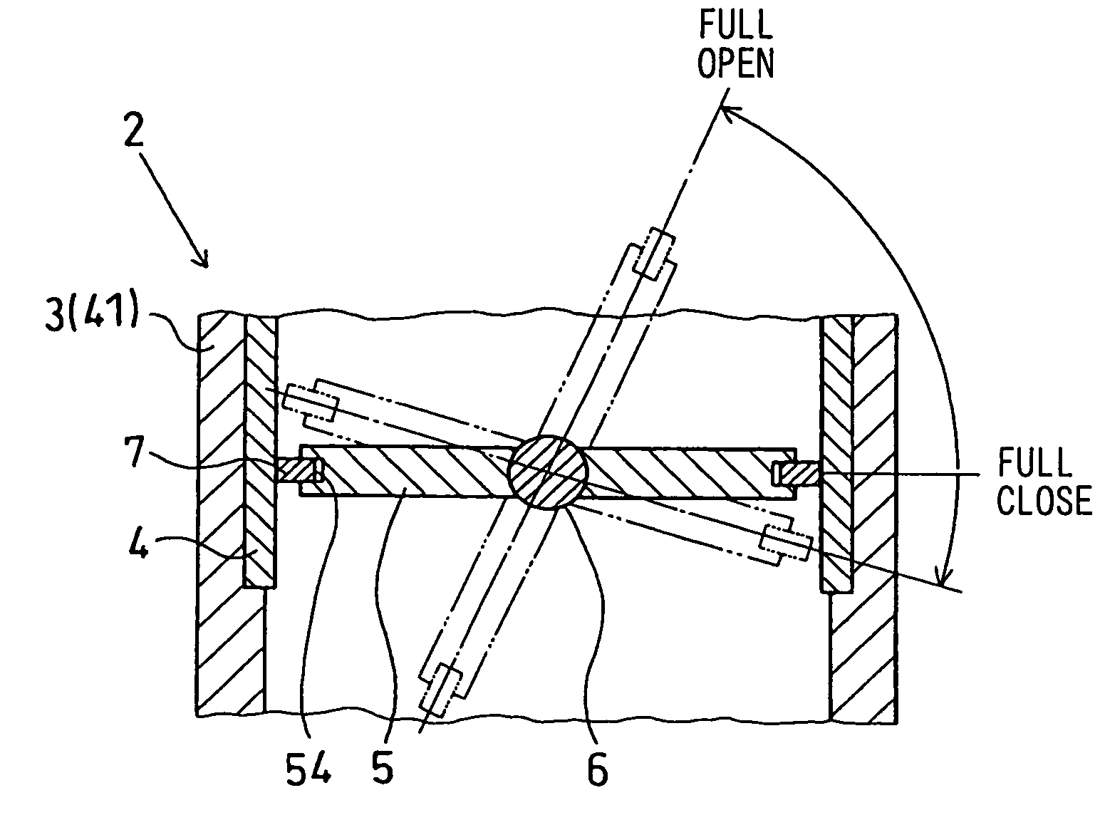
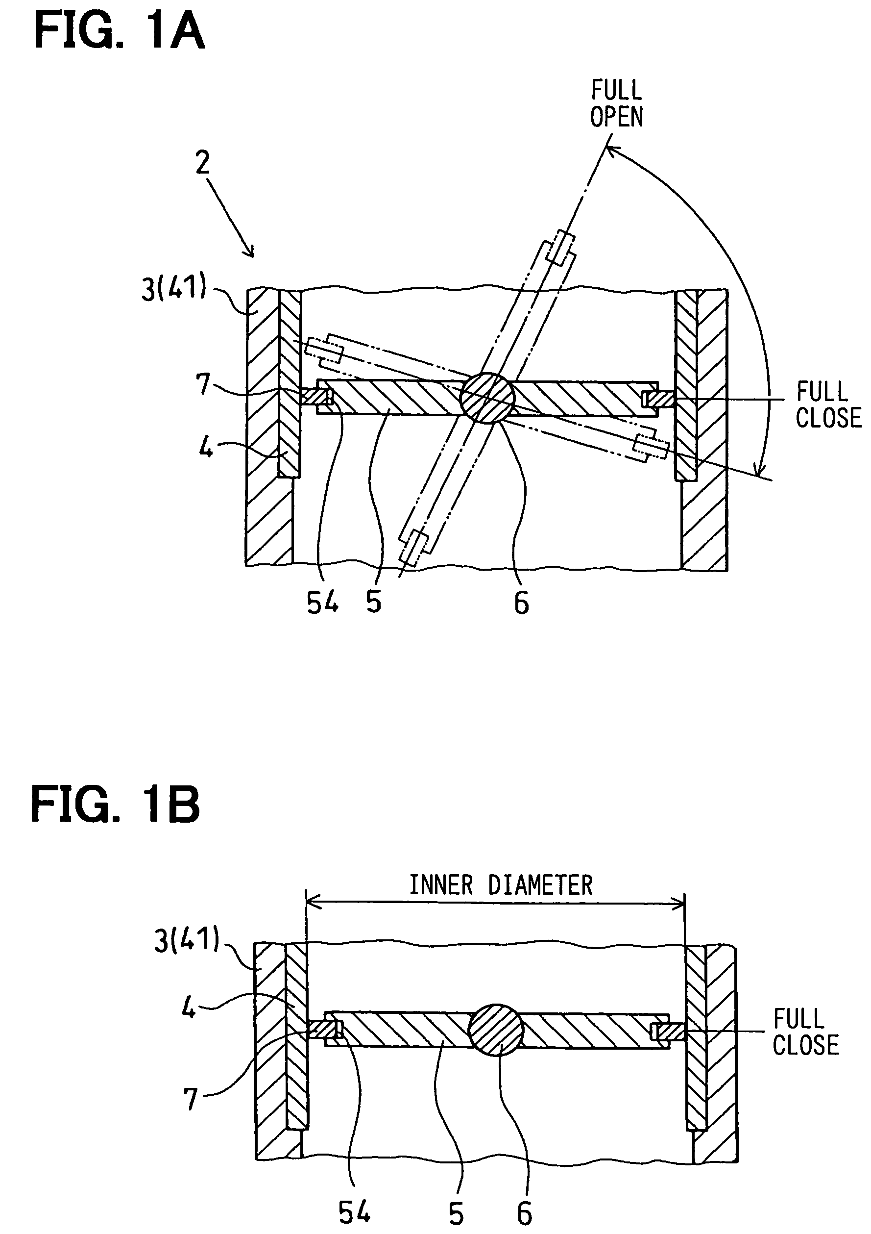
[0068]The emission gas recycling equipment according to this embodiment includes a return spring (not shown) as valve position holding means for stopping the butterfly valve 5 at the valve stop position passed over the valve full close position when the engine stops. In this case, the valve stop position is a position, at which the butterfly valve 5 is rotated by a predetermined rotation angle from the valve full close position in the valve closing direction. The return spring applies a force to the butterfly valve 5 in the returning direction from the valve full open position to the valve stop position across the valve full close position.

[0069]The equipment includes two protrusions (i.e., protruding portions, that are guides such as a rib) 71, 72 as the ring outer diameter ho...

third embodiment

[0072](Third Embodiment)

[0073]FIGS. 5A and 5B show a main part of an emission gas recycling amount control valve in emission gas recycling equipment according to a third embodiment of the present invention.

[0074]Emission gas recycling equipment according to this embodiment includes a return spring (not shown) as valve position holding means for stopping the butterfly valve 5 at the valve stop position passed over the valve full close position when the engine stops, similar to the second embodiment. In this case, the valve stop position is a position, at which the butterfly valve 5 is rotated by a predetermined rotation angle from the valve full close position in the valve closing direction. The return spring applies a force to the butterfly valve 5 in the returning direction from the valve full open position to the valve stop position across the valve full close position.

[0075]Further, the equipment includes a seal ring construction as the ring outer diameter holding means. The ring...


PUM


Abstract

Emission gas recycling equipment includes a passage for recycling a part of an emission gas and a control valve for controlling an amount of the part of the emission gas. The control valve includes: a housing having a pipe portion; a butterfly valve accommodated in the pipe portion rotatable in a first direction and a second direction; a seal ring for sealing a clearance; and valve open / close operation means for stopping the butterfly valve at the valve full close position after the valve open / close operation means operates the butterfly valve to open and to close equal to or more than one cycle across the valve full close position at the time when the engine stops or after the engine stops.

Description

CROSS REFERENCE TO RELATED APPLICATION[0001]This application is based on Japanese Patent Application No. 2004-42588 filed on Feb. 19, 2004, the disclosure of which is incorporated herein by reference.[0002]1. Field of the Invention[0003]The present invention relates to emission gas recycling equipment having a butterfly valve.[0004]2. Background of the Invention[0005]Emission gas recycling equipment according to a related art is well-known. In the equipment, an emission gas recycling gas (i.e., EGR gas) as a part of the emission gas flowing through an exhaust pipe of an engine is mixed into an intake air flowing through an intake pipe so that the maximum combustion temperature is reduced. Thus, toxic substance (e.g., a nitrogen oxide) included in the emission gas is reduced. However, when the emission gas is recycled, engine power is reduced, and driving performance of the engine is reduced. Therefore, it is required to control an amount of the recycling emission gas (i.e., an EGR a...

Claims


Application Information

Patent Timeline
Patent Type & Authority Patents(United States)
IPC IPC(8): F02M25/07
CPCF02D9/1045F02M25/0793F02M25/0701F02M25/0795Y02T10/121F02M25/0773F02M26/50F02M26/54F02M26/70F02M26/73E21B7/025E21B10/02
Inventor NANBA, KUNIOMAEDA, KAZUTOHASHIMOTO, KOJISAKAI, TATSUO
Owner DENSO CORP
Why Eureka
Try Eureka