Switching regulator with average current mode control

a switching regulator and mode control technology, applied in the direction of power conversion systems, instruments, dc-dc conversion, etc., can solve problems affecting the performance of switching regulators

Active Publication Date: 2007-01-30
VOLTERRA SEMICONDUCTOR
View PDF9 Cites 39 Cited by
  • Summary
  • Abstract
  • Description
  • Claims
  • Application Information

AI Technical Summary

Problems solved by technology

These additional dependencies affect the performance of the switching regulator.

Method used


Image

  • Switching regulator with average current mode control
  • Switching regulator with average current mode control
  • Switching regulator with average current mode control

Examples


Embodiment Construction

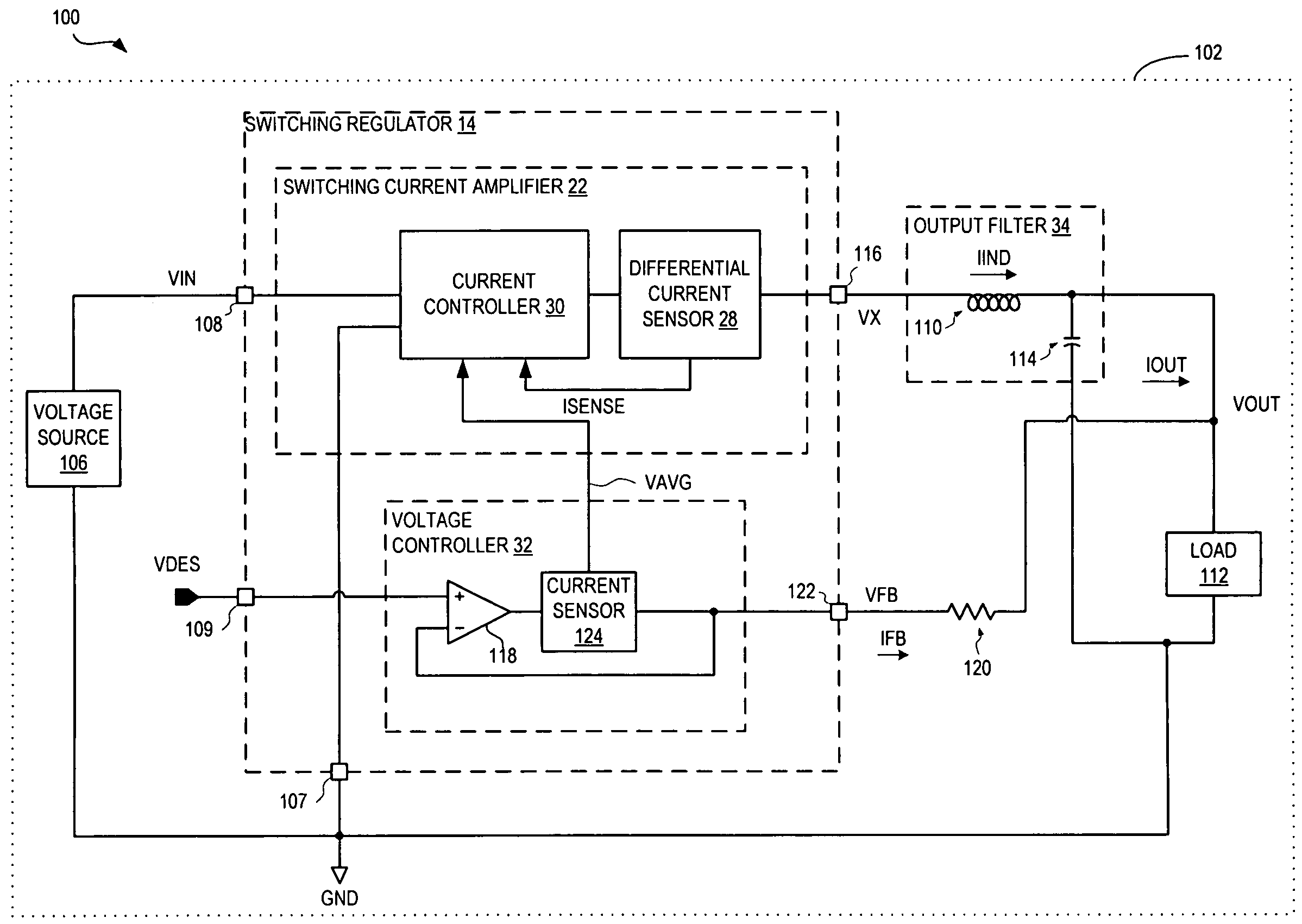
[0020]Certain of the systems and methods described herein employ a switching device that maintains an average current through an output terminal by alternately connecting the output terminal between a first supply rail, such as a voltage source terminal and a second supply rail, such as a ground terminal. A p-type power field-effect transistor (“FET”) may be used to connect the output terminal to the voltage source terminal and an n-type power FET may be used to connect the output terminal to the ground terminal. The p-type power FET and the n-type power FET operate on a mutually exclusively basis as follows: when the current through the p-type power FET reaches a desired average output current plus an offset, the p-type power FET is turned off and the n-type power FET is turned on; when the current through the n-type power FET reaches the desired average output current minus the offset, the n-type power FET is turned off and the p-type power FET is turned on again. The current outp...


PUM


Abstract

A system and method control an output voltage across a load using current mode control to control current through an output filter connected to the load. The output voltage across the load is compared with a reference voltage to generate a reference current signal indicative of a desired average current through the load. A control signal is generated to indicate when an output current is greater than the desired output current. The output filter is alternately coupled to a first supply rail and to a second supply rail in response to the control signal to generate an average current through the load.

Description

RELATED APPLICATIONS[0001]This application claims priority to U.S. provisional application Ser. No. 60 / 495,029, filed 14 Aug. 2003 and hereby incorporated by reference.BACKGROUND OF THE INVENTION[0002]Switching regulators are used to convert a direct current (DC) voltage into a different, stable DC voltage with high efficiency. They are often used in electronics, such as mobile phones and computer equipment.[0003]Switching regulators generally use one or more switching components, such as field effect transistors (FETs) or metal-oxide semiconductor FETs (MOSFETs) (collectively, FETs) to alternately couple and decouple a voltage source to a load. An output filter, such as an inductor and a capacitor, removes high frequency switching noise to produce the desired average output voltage.[0004]A controller controls the switching components to maintain a substantially average output voltage over the load. A feedback loop provides an input to the controller. The feedback loop generally sen...

Claims


Application Information

Patent Timeline
Patent Type & Authority Patents(United States)
IPC IPC(8): G05F1/59
CPCH02M3/156H02M2001/0009H02M1/0009
Inventor MCJIMSEY, MICHAEL DAVID
Owner VOLTERRA SEMICONDUCTOR
Why Eureka
Try Eureka