Extendable shaft

a technology of extension shaft and extension shaft, which is applied in the direction of couplings, manufacturing tools, transportation and packaging, etc., can solve the problems of reducing the slide resistance between the first and the second shaft sections, the diametrically contractible portion can be deformed in an amount according, and the slide resistance can be reduced. , to achieve the effect of preventing the occurrence, reducing the slide resistance, and low clamping for

Inactive Publication Date: 2007-02-06
JTEKT CORP
View PDF11 Cites 12 Cited by
  • Summary
  • Abstract
  • Description
  • Claims
  • Application Information

AI Technical Summary

Benefits of technology

[0011]According to this embodiment, the thin-wall portion is provided so as to expedite the deformation of the diametrically contractible portion. Even though a fit portion between the internal and external splines suffers heavy wear, therefore, the diametrically contractible portion can be deformed in an amount according to the amount of wear. As a result, there may be ensured a long term prevention of the occurrence of play between the first and the second shaft sections despite the occurrence of wear.
[0012]Since the diametrically contractible portion is prone to yield, a clamping member having a low clamping force may be employed. This results in a reduced slide resistance between the first and the second shaft sections. Since the thin-wall portion is formed in a part of the diametrically contractible portion, the thin-wall portion may be formed at a lower cost as compared with a case where the whole body of the diametrically contractible portion is formed thin.

Problems solved by technology

Even though a fit portion between the internal and external splines suffers heavy wear, therefore, the diametrically contractible portion can be deformed in an amount according to the amount of wear.
This results in a reduced slide resistance between the first and the second shaft sections.

Method used


Image

  • Extendable shaft
  • Extendable shaft
  • Extendable shaft

Examples


Embodiment Construction

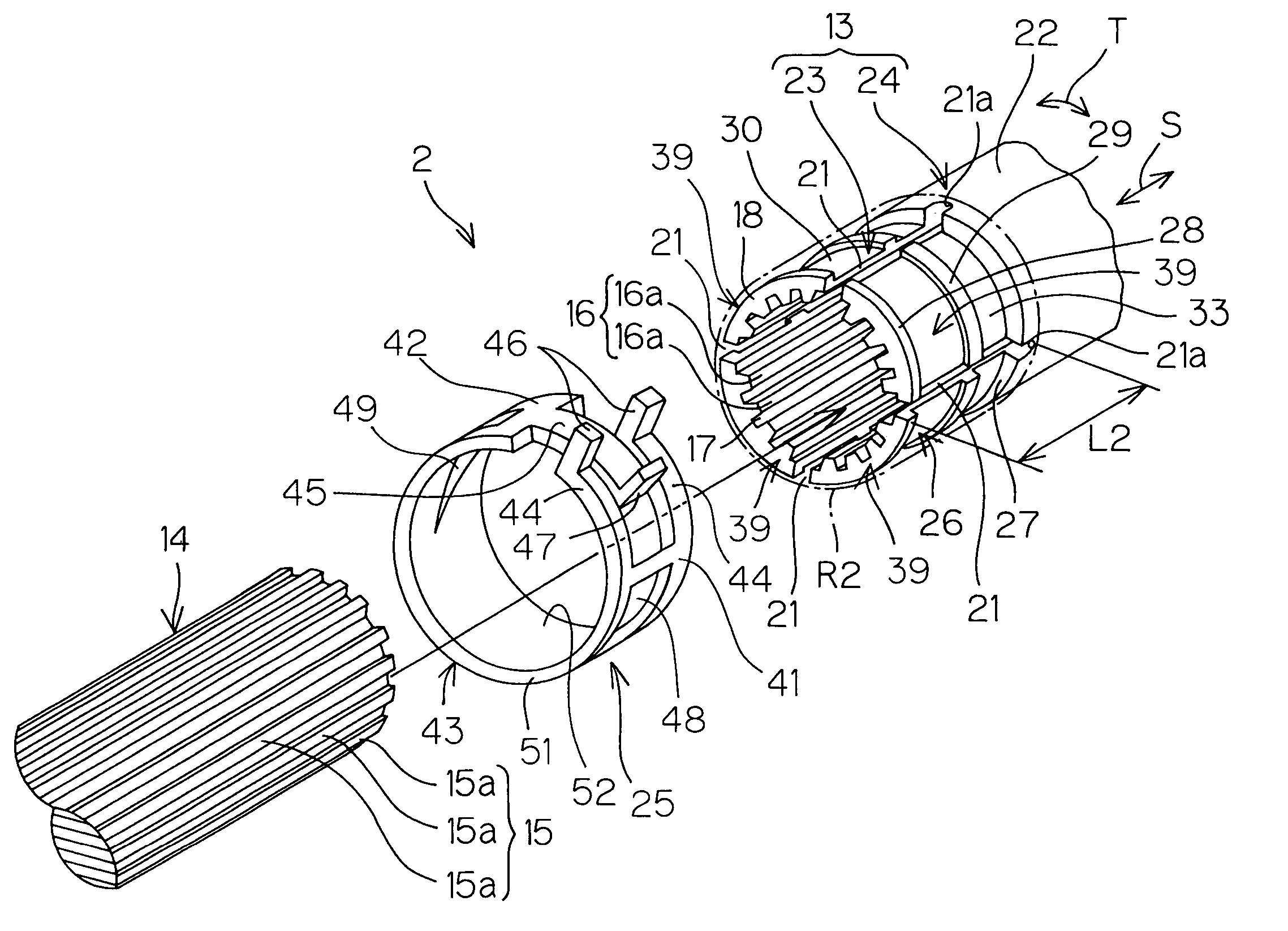
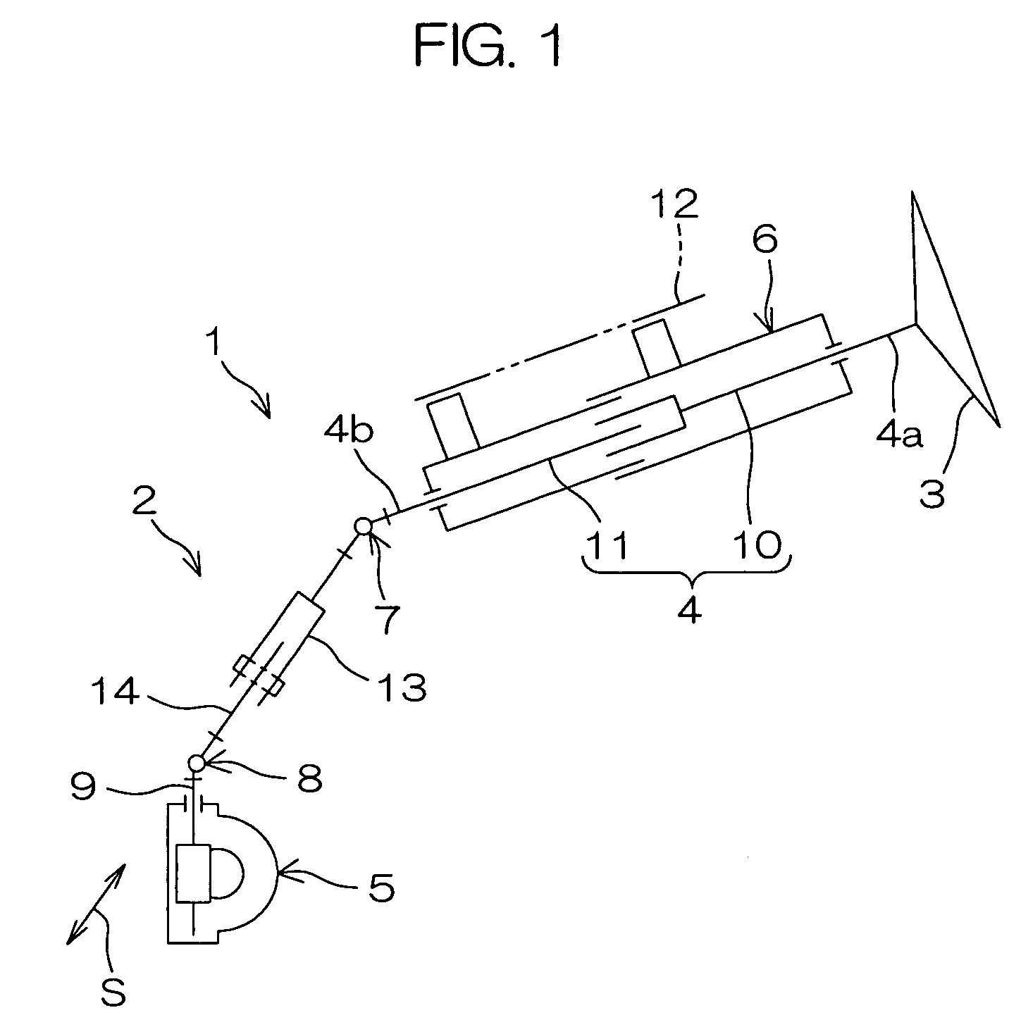
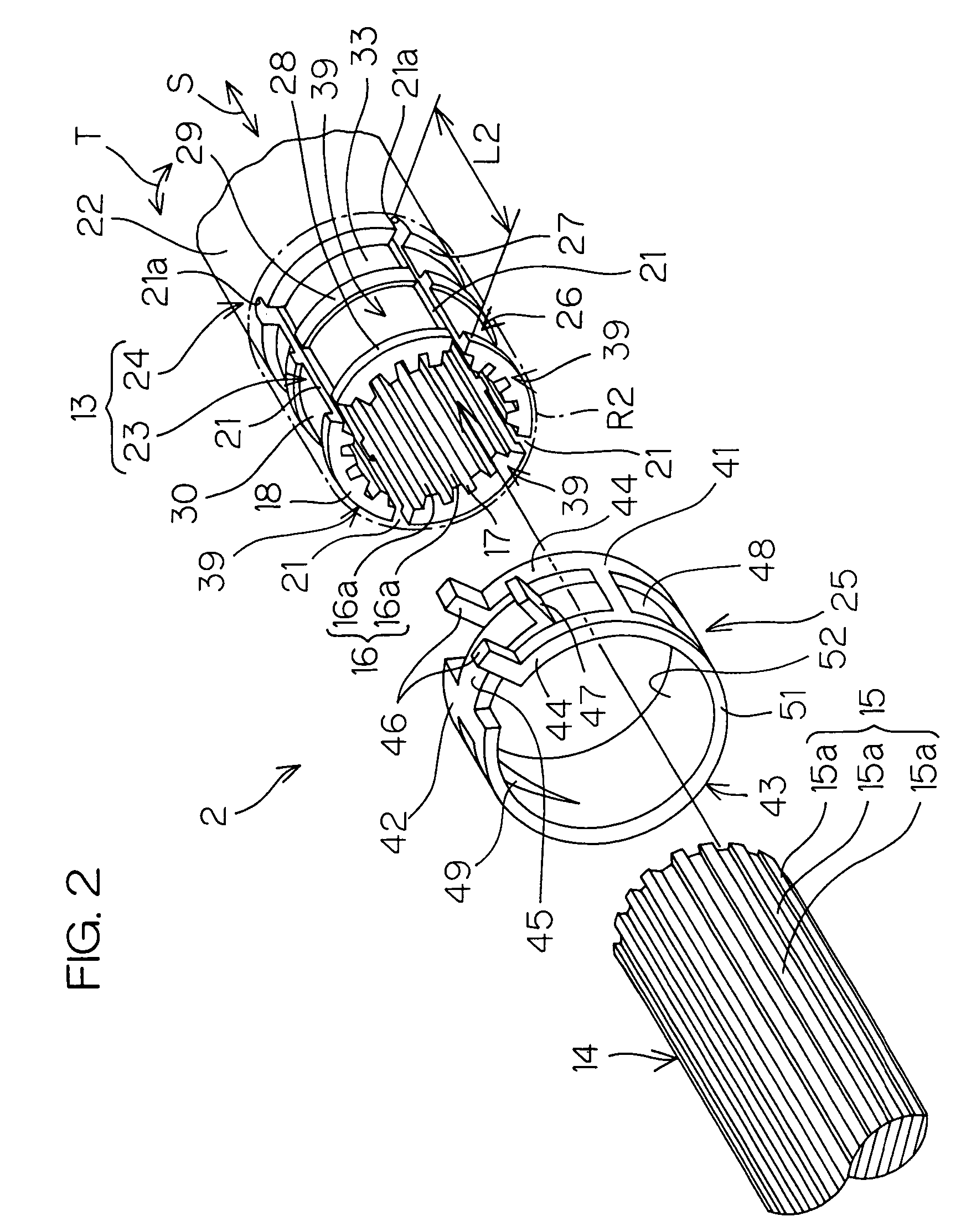
[0026]An intermediate shaft as an extendable shaft according to one embodiment of the present invention will hereinbelow be described in details with reference to the accompanying drawings. FIG. 1 is a schematic diagram showing a general arrangement of a vehicular steering assembly including the aforesaid intermediate shaft.

[0027]Referring to FIG. 1, a vehicular steering assembly 1 includes an intermediate shaft 2. When a steering torque is applied to a steering wheel 3 in order to steer road wheels (not shown), the intermediate shaft 2 transmits the steering torque from a steering shaft 4 coupled to the steering wheel 3 at one end 4a thereof to a steering mechanism 5 for steering the road wheels.

[0028]The vehicular steering assembly 1 includes the aforesaid steering shaft 4 for transmitting the steering torque, and a steering column 6 rotatably supporting the steering shaft 4 pierced therethrough. An other end 4b of the steering shaft 4 is connected with a rotary shaft 9 of the afo...


PUM


Abstract

An extendable shaft includes a first and a second shaft sections aligned on the same axis. External splines on an outer periphery of the first shaft section engage external splines on an inner periphery of the second shaft section. The first shaft section includes a slit extended from an opening end thereof for a predetermined length along an axial direction. A diametrically contractible portion adapted for elastic reduction in diameter is provided in a region ranging from the opening end of the first shaft section to place away therefrom by the predetermined length along the axial direction. A thin-wall portion is formed in a part of the diametrically contractible portion. A clamping member elastically clamps the diametrically contractible portion.

Description

BACKGROUND OF THE INVENTION[0001]1. Field of the Invention[0002]The present invention relates to an extendable shaft for use, for example, in steering assembly for vehicles.[0003]2. Description of Related Art[0004]An extendable shaft includes a type which includes a first tubular shaft section and a second shaft section inserted and fitted in the first tubular shaft section. The first and the second shaft sections are engaged with each other via spline fit so as to be slidably movable relative to each other.[0005]Some of the conventional extendable shafts have a play elimination function for obviating the occurrence of play at a spline fit portion. Specifically, the aforesaid first shaft section is formed with a plurality of slits at an end thereof, and the slits are opening toward an opening end and extending for a predetermined length along an axial direction. This involves the formation of a plurality of cantilevered tongues, elastically deformable, between the slits.[0006]In ord...

Claims


Application Information

Patent Timeline
Patent Type & Authority Patents(United States)
IPC IPC(8): B25G3/28B62D1/185F16C3/03F16D3/06
CPCB62D1/185F16D3/06F16C3/03Y10T403/7033F16C2326/24
Inventor MINAMOTO, NOBORUTOKIOKA, RYOUICHIHIRAKUSHI, SHUZO
Owner JTEKT CORP
Why Eureka
Try Eureka