Jump rope simulator

a simulator and jump rope technology, applied in the field of jump rope simulators, can solve the problems of losing the rhythm and timing of exercise workout, falling over the rope, etc., and achieve the effect of convenient storage and transportation, easy addition or removal by a user, and convenient storage and transportation

Inactive Publication Date: 2007-02-06
JOY CYNTHIA L +2
View PDF14 Cites 11 Cited by
  • Summary
  • Abstract
  • Description
  • Claims
  • Application Information

AI Technical Summary

Benefits of technology

[0009]According to an embodiment of the present invention, the beads are attached to each other through the use of a simple, low-cost interlocking snap-fit mechanism on the beads. One end of each bead has a spherical protrusion and the other end of each bead has a socket that accepts the spherical protrusion. The first end of one bead plugs into the second end of another bead, and the beads can be easily added or removed by a user without the use of any tools. In this way, a user can adjust the number of beads on the unit and thus adjust the length of the unit to accommodate the user's height. Preferably the bodies of the tubular beads have accordion-like pleated folds to provide for flexibility in the unit so that the unit moves freely and mimics the feel of a rope during use and is also easy to store and transport between uses.
[0010]According to another embodiment of the present invention, the beads are attached to each other with the use of threaded screw-type male and female ends on the beads. One end of each bead is a threaded male end and the other end of each bead is a threaded female socket. The first end of one bead screws into the second end of another bead, and the beads can be easily added or removed by a user without the use of any tools. In this way, a user can adjust the number of beads on the unit and thus adjust the length of the unit to accommodate the user's height. Preferably the bodies of the tubular beads have accordion-like pleated folds to provide for flexibility in the unit so that the unit moves freely and mimics the feel of a rope during use and is also easy to store and transport between uses.
[0011]According to yet another embodiment of the present invention, the beads are attached to each other through the use of a screw-type coupler between the beads. Both ends of each bead are threaded female sockets. A tubular coupling screw having two threaded male ends is used to easily link together two beads. Alternatively, both ends of each bead are threaded male ends, and a tubular coupling screw having two threaded female ends is used to easily link together two beads. This simple low-cost connecting mechan

Problems solved by technology

If the user should misjudge when the rope is under his feet, he will tr

Method used


Image

  • Jump rope simulator
  • Jump rope simulator
  • Jump rope simulator

Examples


Embodiment Construction

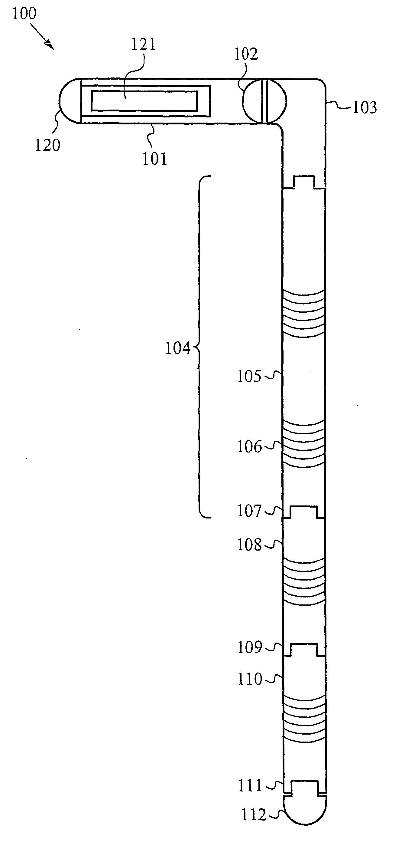
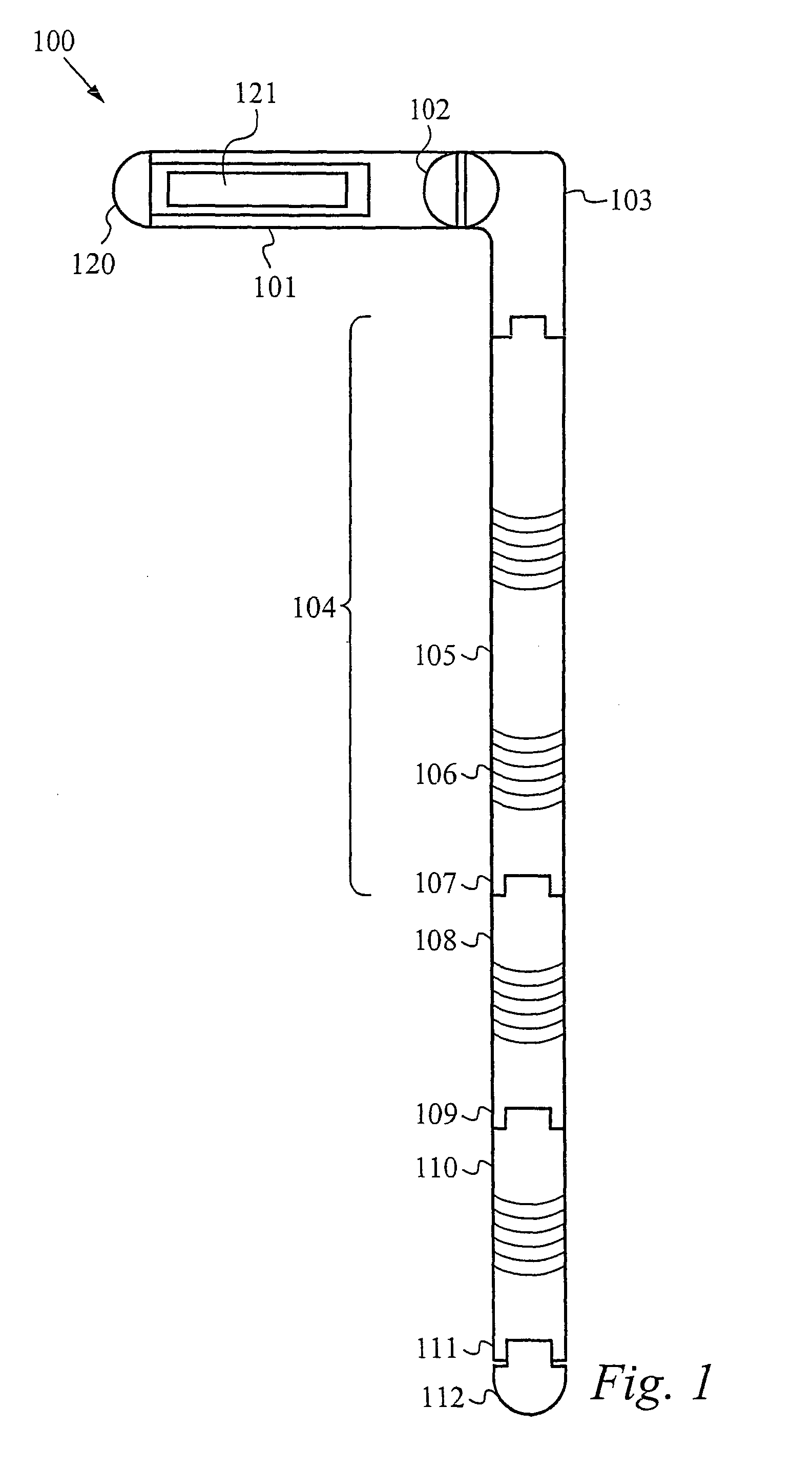
[0019]FIG. 1 illustrates a jump rope simulator 100 in accordance with the preferred embodiment of the present invention. The jump rope simulator unit 100 has a handle that is L-shaped and padded on the long side 101 with a resilient material in an ergonomic shape that fits comfortably in a user's hand during exercise workouts. The handle has a short side 103 that is attached to the long side of the handle 101 by a ball-bearing joint 102 which allows the short side of the handle 103 to rotate 360 degrees around the longitudinal axis of the long side of the handle. A sound mechanism is preferably built into the ball-bearing joint 102 such that for each rotation of the handle 103 around the long side of the handle, an audible sound is output. The rotatable handle is designed so that when the user rotates the individual unit, the far end of the unit is prevented from impacting the user's legs. The long side of the handle 101 is preferably hollow and has a removable end-cap 120. A weight...


PUM


Abstract

A jump rope simulator for aerobic and anaerobic exercise having a hand-held unit comprising a handle, a base length connected to the handle, and one or more concatenated extension lengths attached to the base length. To exercise, the user grasps one or two units, imitates the motions of swinging a conventional jump rope, and jumps up and down, but there is no risk to the user of tripping over a rope as with a conventional jump rope. If the user desires, two units may also be linked together with an easily attachable connector to form a device similar to a conventional jump rope. A user can quickly convert between the two configurations of the jump rope simulator.

Description

RELATED APPLICATIONS[0001]This Patent Application claims priority under 35 U.S.C. 119 (e) of the co-pending U.S. Provisional Patent Application Ser. No. 60 / 403,749, filed Aug. 13, 2002, and entitled, “JUMP ROPE SIMULATOR AND METHOD OF EXERCISE.” The Provisional Patent Application Ser. No. 60 / 403,749, filed Aug. 13, 2002, and entitled, “JUMP ROPE SIMULATOR AND METHOD OF EXERCISE” is also hereby incorporated by reference.FIELD OF THE INVENTION[0002]The present invention relates generally to aerobic and anaerobic exercise devices, and more specifically to a new jump rope simulator for providing aerobic and anaerobic exercise.BACKGROUND OF THE INVENTION[0003]Traditional jump ropes are usually made from a single length of rope with handles at both ends for the user to grip. The user holds the rope by the handles, swings the rope over his head and then under his feet in a continuous motion, and jumps over the rope every time it passes under his feet. If the user should misjudge when the r...

Claims


Application Information

Patent Timeline
IPC IPC(8): A63B5/20
CPCA63B5/20A63B2071/0625
Inventor JOY, CYNTHIA L.JOHNSON, KENNETH R.SOPHIR, F. MICHAEL
Owner JOY CYNTHIA L
Why Eureka
Try Eureka