
Compact accelerator

a compact accelerator and accelerator technology, applied in accelerators, electric discharge tubes, electrical equipment, etc., can solve the problems of affecting beam quality and performance, overall device less than optimal for the intended use of accelerating charged particles, and limited use of beams

Active Publication Date: 2007-02-06
LAWRENCE LIVERMORE NAT SECURITY LLC
View PDF5 Cites 79 Cited by
  • Summary
  • Abstract
  • Description
  • Claims
  • Application Information

AI Technical Summary

Benefits of technology

"The present invention provides a compact linear accelerator that includes a Blumlein module with a specific arrangement of planar conductor strips and dielectric strips. The module guides an electrical signal wave from one end to the other to control the output pulse at the other end. The invention also includes a high voltage power supply and switching means to initiate a reverse polarity wave in the dielectric strips. The technical effects of the invention include a more efficient and compact linear accelerator with improved control over output pulse characteristics."

Problems solved by technology

The existing dielectric wall accelerators, such as the Carder DWA, however, have certain inherent problems which can affect beam quality and performance.
In particular, several problems exist in the disc-shaped geometry of the Carder DWA which make the overall device less than optimum for the intended use of accelerating charged particles.
Instead, a charged particle beam traversing the electric field created by such a structure will receive a time varying energy gain, which can prevent an accelerator system from properly transporting such beam, and making such beams of limited use.
The disc-shaped Blumlein structure of Carder can cause excessive levels of electrical energy to be stored in the system.
Such excess energy can have a detrimental effect on the performance and reliability of the overall device, which can lead to premature failure of the system.
This problem is further compounded when long acceleration pulses are required since the output pulse length of this disc-shaped Blumlein structure is directly related to the radial extent from the central hole.
As the preferred embodiment of initiating the switch is the use of a laser or other similar device, a highly complex distribution system is required.
Moreover, a long pulse structure requires large dielectric sheets for which fabrication is difficult.
This can also increase the weight of such a structure.
While some of the long pulse disadvantages can be alleviated by the use of spiral grooves in all three of the conductors in the asymmetric Blumlein, this can result in a destructive layer-to-layer coupling which can inhibit the operation.

Method used


Image

  • Compact accelerator
  • Compact accelerator
  • Compact accelerator

Examples


Embodiment Construction

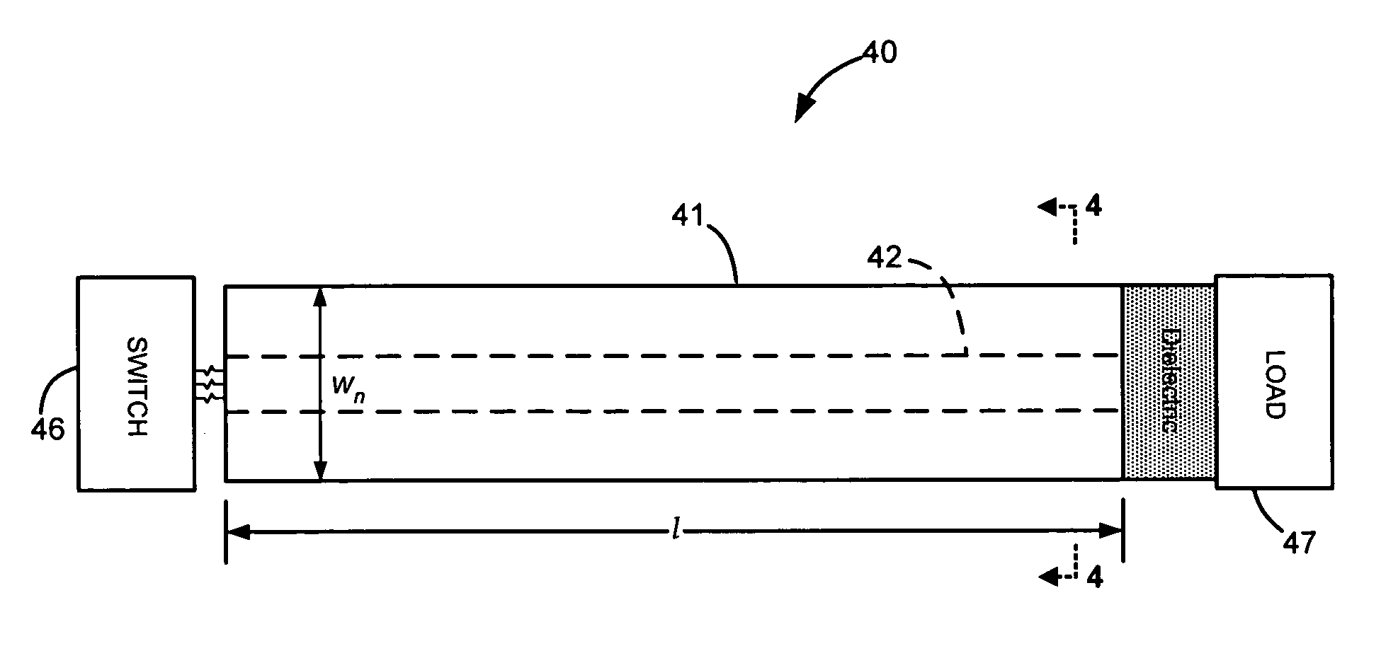
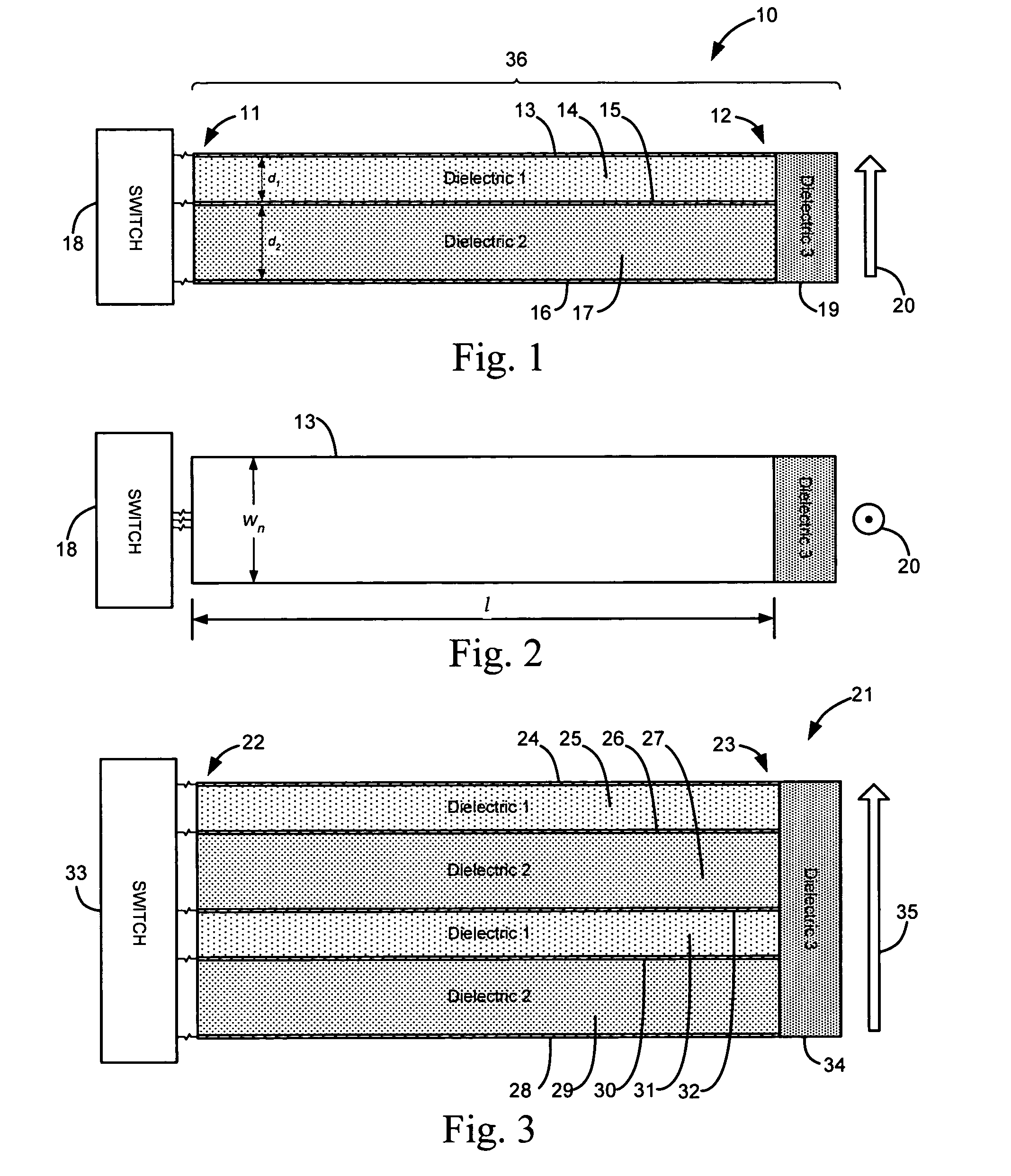
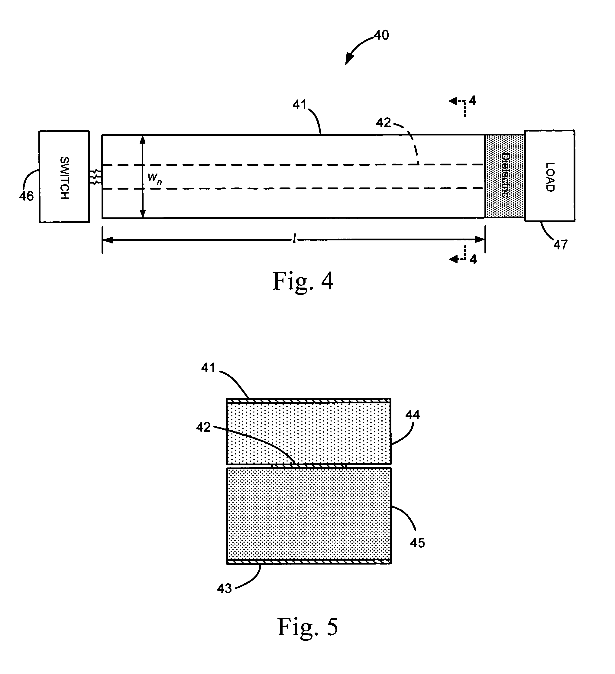
[0025]Turning now to the drawings, FIGS. 1–2 show a first exemplary embodiment of the compact linear accelerator of the present invention, generally indicated at reference character 10, and comprising a single Blumlein module 36 connected to a switch 18. The compact accelerator also includes a suitable high voltage supply (not shown) providing a high voltage potential to the Blumlein module 36 via the switch 18. Generally, the Blumlein module has a strip configuration, i.e. a long narrow geometry, typically of uniform width but not necessarily so. The particular Blumlein module 11 shown in FIGS. 1 and 2 has an elongated beam or plank-like linear configuration extending between a first end 11 and a second end 12, and having a relatively narrow width, wn (FIGS. 2, 4) compared to the length, l. This strip-shaped configuration of the Blumlein module operates to guide a propagating electrical signal wave from the first end 11 to the second end 12, and thereby control the output pulse at ...


PUM


Abstract

A compact linear accelerator having at least one strip-shaped Blumlein module which guides a propagating wavefront between first and second ends and controls the output pulse at the second end. Each Blumlein module has first, second, and third planar conductor strips, with a first dielectric strip between the first and second conductor strips, and a second dielectric strip between the second and third conductor strips. Additionally, the compact linear accelerator includes a high voltage power supply connected to charge the second conductor strip to a high potential, and a switch for switching the high potential in the second conductor strip to at least one of the first and third conductor strips so as to initiate a propagating reverse polarity wavefront(s) in the corresponding dielectric strip(s).

Description

I. CLAIM OF PRIORITY IN PROVISIONAL APPLICATION[0001]This application claims priority in provisional application no. 60 / 536,943, filed on Jan. 15, 2004, entitled “Improved Compact Accelerator” by George J. Caporaso et al.[0002]The United States Government has rights in this invention pursuant to Contract No. W-7405-ENG-48 between the United States Department of Energy and the University of California for the operation of Lawrence Livermore National Laboratory.II. FIELD OF THE INVENTION[0003]The present invention relates to linear accelerators and more particularly to dielectric wall accelerators and pulse-forming lines that operate at high gradients to feed an accelerating pulse down an insulating wall.III. BACKGROUND OF THE INVENTION[0004]Particle accelerators are used to increase the energy of electrically-charged atomic particles, e.g., electrons, protons, or charged atomic nuclei, so that they can be studied by nuclear and particle physicists. High energy electrically-charged at...

Claims


Application Information

Patent Timeline
Patent Type & Authority Patents(United States)
IPC IPC(8): H05H9/00H01J23/00H05H7/00H05H9/02
CPCH05H9/02H05H7/00
Inventor CAPORASO, GEORGE J.SAMPAYAN, STEPHEN E.KIRBIE, HUGH C.
Owner LAWRENCE LIVERMORE NAT SECURITY LLC
Learn More