
Vacuum tube power amplifier switchable between push-pull and single ended configurations

a technology of vacuum tubes and power amplifiers, which is applied in amplifiers, amplifiers with semiconductor devices/discharge tubes, amplifiers, etc., can solve the problems of low frequency roll-off, reduced magnetic flux capability, and failure to switch between push-pull and single-ended construction, etc., to achieve touch sensitive dynamic nuance, increase loudness and distortion, and notable “fat”.

Active Publication Date: 2007-02-06
GIBSON BRANDS
View PDF11 Cites 10 Cited by
  • Summary
  • Abstract
  • Description
  • Claims
  • Application Information

AI Technical Summary

Benefits of technology

"The present invention offers an amplifier that can provide both desirable power section distortion and harmonic tonal characteristics of push-pull and single-ended in a single amplifier. The amplifier can be reconfigured at the flip of a switch to provide ample power for live performances or have substantially reduced power for recording or practicing. The invention also solves the technical problem of accommodating single-ended operation by including a gap in the core of a push-pull transformer, which reduces its magnetic flux capability and causes low frequency roll-off and a general loss of efficiency. The present invention overcomes this limitation while simultaneously solving the problems of providing appropriate drive, signal, and balance conditions for both single-ended and push-pull operation."

Problems solved by technology

Unfortunately, there are serious technical obstacles that, until the present invention, have prevented successful switching between push-pull and single-ended construction.
Unfortunately, accommodating single-ended operation by including a gap in the core of a push-pull transformer greatly reduces its magnetic flux capability and causes low frequency roll-off and a general loss of efficiency.

Method used


Image

  • Vacuum tube power amplifier switchable between push-pull and single ended configurations
  • Vacuum tube power amplifier switchable between push-pull and single ended configurations

Examples


Embodiment Construction

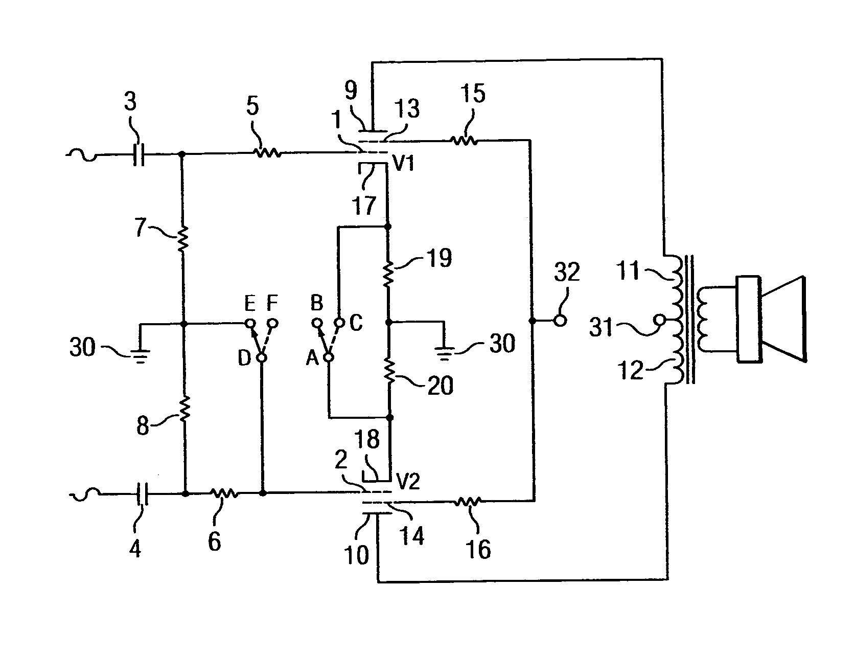
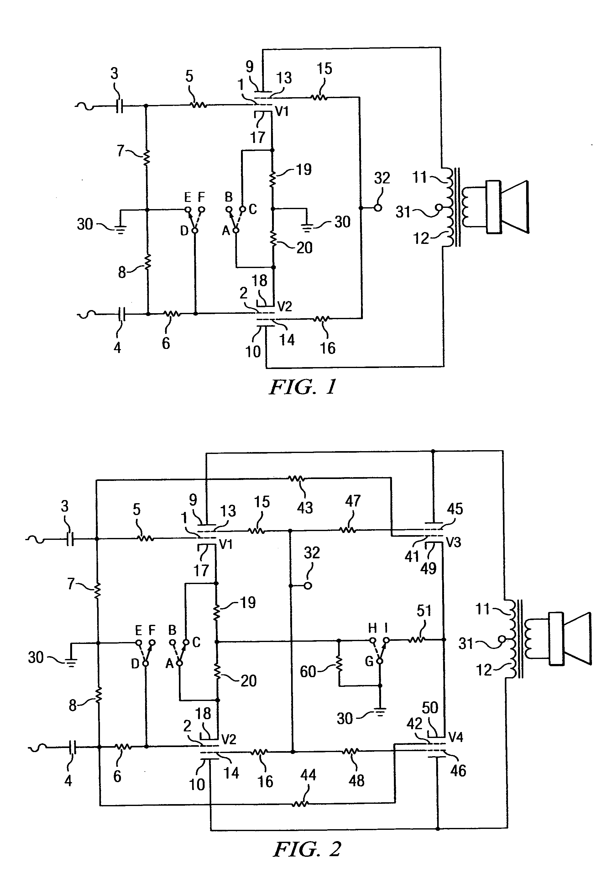
[0015]Referring to FIG. 1, opposing phase push-pull AC signals are provided for the signal grids 1, 2 of vacuum tube power pentodes V1 and V2 respectively. The AC signals are coupled through blocking capacitors 3, 4 and grid stop resistors 5, 6. Grid leak resistors 7, 8 provide DC reference to ground 30 for the grids 1, 2. Anodes 9, 10 of pentodes V1 and V2 are fed DC high voltage through respective halves of the output of transformer primary winding 11, 12. DC voltage from the power supply (not shown) enters the output transformer primary winding 11, 12 through center tap 31. Screen grids 13, 14 are coupled to the high voltage DC source at 32 via current limiting resistors 15 and 16. Cathodes 17, 18 are coupled to ground 30 through respective cathode bias resistors 19, 20. Switches A, B, C and D, E, F operate in conjunction with each other and may be a double pole double throw (DPDT) relay device. When configured as shown by the arrows, connection D to E effectively grounds the gri...


PUM


Abstract

A vacuum tube power amplifier with a user-operable switch and a single output transformer which selectively provides push-pull or single ended configurations for driving a loudspeaker.

Description

FIELD OF THE INVENTION[0001]This invention relates to the use of vacuum tubes in audio power amplifiers, particularly for use in conjunction with an electric guitar.BACKGROUND AND BRIEF DESCRIPTION OF THE PRIOR ART[0002]Vacuum tube audio amplifiers generally utilize push-pull output configurations as the most economical method of producing ample power. The benefits of push-pull are well known in the art and require no repetition herein. It is sufficient to say that commercial amplifiers offering power levels even as low as 15 watts will use a push-pull pair of output tubes, though one larger tube in a single-ended configuration could also provide similar power. It can be safely asserted that virtually all commercial audio amplifiers providing more than 20 watts are of the push-pull variety.[0003]In contrast, single-ended vacuum tube output sections have previously been used mostly in 5 to 8 watt so-called “beginner” guitar amplifiers, which offer a stark economy of overall design. N...

Claims


Application Information

Patent Timeline
Patent Type & Authority Patents(United States)
IPC IPC(8): H03F3/30H03F3/22
CPCH03F3/22H03F3/28
Inventor SMITH, RANDALL C.
Owner GIBSON BRANDS
Learn More