Apparatus comprising a tunable nanomechanical near-field grating and method for controlling far-field emission

a nanomechanical, near-field grating technology, applied in the field of optics, can solve the problems of reducing the diffraction rate, affecting the diffraction rate,

Active Publication Date: 2007-02-06
NAT TECH & ENG SOLUTIONS OF SANDIA LLC
View PDF12 Cites 26 Cited by
  • Summary
  • Abstract
  • Description
  • Claims
  • Application Information

AI Technical Summary

Benefits of technology

[0017]The illustrative embodiment of the present invention is a tunable nanomechanical near-field grating and method for causing changes in the far-field emission of the grating in response to very small changes in element spacing within the near-field of the grating.

Problems solved by technology

In other words, diffraction increases fringing in the image of the aperture to such an extent that the aperture is no longer perfectly imaged.
These emerging waves undergo constructive and destructive interference based on their relative phases.
For example, if the peak of a wave from a first aperture meets a valley of a wave from a second aperture, the two waves will cancel each other out (i.e., destructive interference).
This behavior—destructive and constructive interference—forms the basis for a diffraction grating, which is a repetitive array of objects, either apertures or opaque obstructions, which produce periodic changes to the phase and / or amplitude of an optical wave that emerges from the grating.
Unfortunately, laterally-deformable gratings have suffered from non-uniform compression due to mechanical irregularities as well as poor reliability due to large induced strains in the grating materials.
As a consequence, the speed of response (i.e., operating bandwidth) and reliability of these tunable diffraction gratings are limited by mechanical considerations, such as the size and mass of the line-elements and the amount of induced strain that is required to affect a desired change in operating characteristic.

Method used


Image

  • Apparatus comprising a tunable nanomechanical near-field grating and method for controlling far-field emission
  • Apparatus comprising a tunable nanomechanical near-field grating and method for controlling far-field emission
  • Apparatus comprising a tunable nanomechanical near-field grating and method for controlling far-field emission

Examples


Embodiment Construction

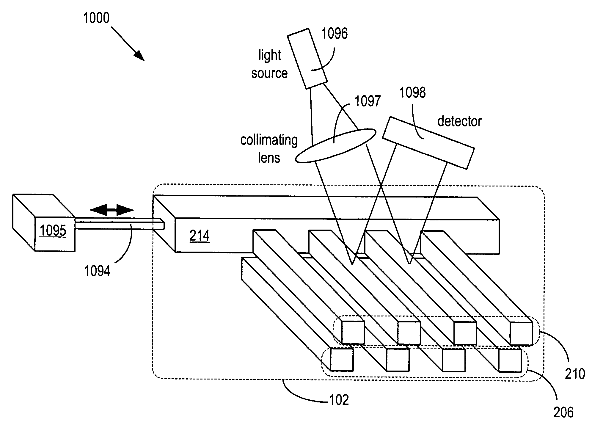
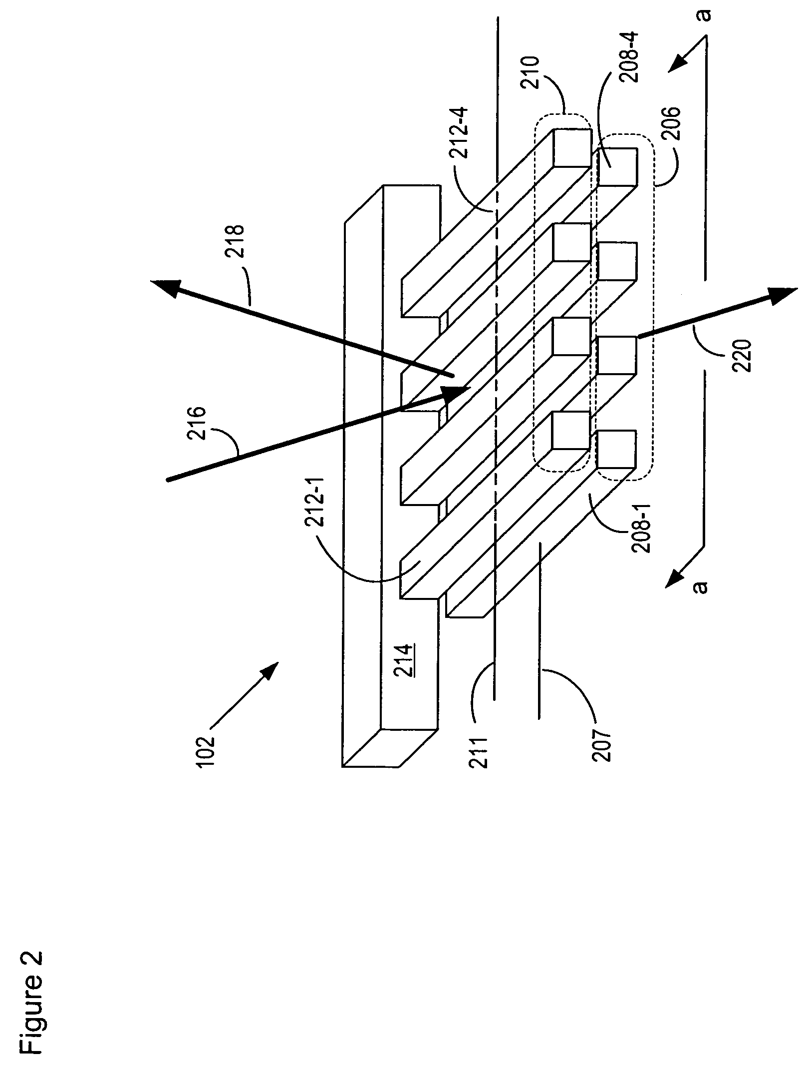
[0032]FIG. 1 depicts a schematic view of a tunable nanomechanical near-field grating in accordance with the illustrative embodiment. As used in this specification, the phrase “nanomechanical near-field grating” is defined as a grating comprising line-elements that have width and thickness less than one micron, and wherein at least some of the line-elements are separated by a distance less than the operating wavelength of the grating.

[0033]Tunable nanomechanical near-field grating 100 comprises nanomechanical near-field grating 102 (hereinafter, “grating”) and motion enabler 104. As depicted in FIG. 2, grating 102 comprises sub-gratings 206 and 208. Sub-grating 206 includes line elements 208-i, i=1,4 (collectively, line-elements 208), which are spaced uniformly along lateral axis 207. Sub-grating 210 includes line-elements 212-i, i=1,4, (collectively, line-elements 212), which are spaced uniformly along lateral axis 211. Line-elements 212 depend from beam 214. Each line-element 208-i...


PUM


Abstract

A tunable nanomechanical near-field grating is disclosed which is capable of varying the intensity of a diffraction mode of an optical output signal. The tunable nanomechanical near-field grating includes two sub-gratings each having line-elements with width and thickness less than the operating wavelength of light with which the grating interacts. Lateral apertures in the two sub-gratings are formed from the space between one line-element of the first sub-grating and at least one line-element of the second sub-grating. One of the sub-gratings is capable of motion such that at least one of aperture width and aperture depth changes, causing a perturbation to the near-field intensity distribution of the tunable nanomechanical near-field grating and a corresponding change to the far-field emission of thereof.

Description

FIELD OF THE INVENTION[0001]The present invention relates to optics in general, and, more particularly, to tunable diffraction gratings.BACKGROUND OF THE INVENTION[0002]As light travels through a uniform material, such as air, it behaves as a series of plane waves traveling in the direction of propagation. When a plane wave meets an obstruction, it undergoes a change due to interaction with that obstruction. Every unobstructed point on the wavefront of the wave can be considered as a source of a secondary spherical wavelet with the same wavelength and phase as the incident wave. The outgoing wavefront is the combination of all of these wavelets.[0003]For example, if a plane wave that is traveling through water strikes a barrier that has a single small aperture (i.e., no wider than the wavelength), the outgoing wave takes a form similar to the wavefront that would be generated if a pebble were dropped into the water at the aperture. The incident plane wave is said to diffract outward...

Claims


Application Information

Patent Timeline
Patent Type & Authority Patents(United States)
IPC IPC(8): G02B5/18G02B26/08
CPCG02B26/0808G02B5/1828
Inventor CARR, DUSTIN WADEBOGART, GREGORY ROBERT
Owner NAT TECH & ENG SOLUTIONS OF SANDIA LLC
Why Eureka
Try Eureka