Apparatus and method for simulation of the control and machine behavior of machine tools and production-line machines

a technology applied in the field of apparatus and methods for simulation of the control and machine behavior of machine tools and production lines, can solve the problems of not always easy to design and implement, the complexity of these machines is constantly increasing, and the inability to achieve realistic representation of the kinematic response of the machine to motion in a way that is not easy to achieve, so as to achieve accurate time, increase the cycle-time of the digital controller, and improve the approximation of reality

Active Publication Date: 2007-02-06
SIEMENS AG
View PDF5 Cites 62 Cited by
  • Summary
  • Abstract
  • Description
  • Claims
  • Application Information

AI Technical Summary

Benefits of technology

[0020]An advantage of the present invention resides in the combination of closed-loop control, such as that provided by PLC and NC controllers, with drive systems and machine models including sensor technology, that can be adapted for use with any axis elements of the machine, both regulated or unregulated axes. Only this combination makes it possible for actual axis values simultaneously produced for the respective drive systems in the mechanism to be processed by a model of the mechanism, resulting in a simulation of the mechanism's response that preserves a good approximation of reality.
[0021]In particular, the combination of control technology, drive technology and mechanism models are applied together for any type of axis: for an axis regulated as to position and / or speed and / or momentum, for example, or for an unregulated axis; and the desired parameters for the digitally-controlled machines are controlled by the outputs of NC- and PLC-control models. The result is that machine components subject to different types of control are thus brought together in a single model through the modeling of their respective drive technologies. Significant characteristics of the machine influence the control cycle of the drive models, such as the mass parameters for modeling real acceleration and speed, for example.
[0022]According to another feature of the present invention, the digital controller may be simulated or emulated by an auxiliary computer or a computer that is separate from the auxiliary computer. Therefore, despite frequent differences in the machine-related control hardware, an apparatus according to the invention can be assembled with identical control hardware, because the original digital controller is not used by the simulator.
[0023]According to another feature of the present invention, the simulation may be configured to operate in real time. Providing a simulation that is carried on in real time permits the observer to see a representation of the production process that is accurately timed.
[0024]According to another feature of the present invention, the cycle-time of the digital controller can be increased. Advantageously, in the event that the auxiliary simulation computer does not have sufficient computing capacity for a real-time simulation, its capacity is advantageously extended if the cycle time of the digital controller is raised and the digital controller is slowed down, in effect, forcing a uniform scaling of the time base of the simulation as a result.
[0025]According to another feature of the present invention, the auxiliary computer may calculate the state variable from the model of the over-all mechanism, to provide a compact configuration for the simulation device.

Problems solved by technology

With the increasing product-quality and economic-efficiency requirements being placed on machine-tool and production-line machine, including robots, the complexity of these machines is constantly increasing.
However, this is not always easy to design and implement.
Since in that operation the modeling of the drive means is neglected and the desired and actual values are implicitly set to be identical, a realistic representation of the machine's kinematic response to motion cannot be achieved that way.

Method used


Image

  • Apparatus and method for simulation of the control and machine behavior of machine tools and production-line machines
  • Apparatus and method for simulation of the control and machine behavior of machine tools and production-line machines
  • Apparatus and method for simulation of the control and machine behavior of machine tools and production-line machines

Examples


Embodiment Construction

[0032]Throughout all the Figures, same or corresponding elements are generally indicated by same reference numerals. These depicted embodiments are to be understood as illustrative of the invention and not as limiting in any way. It should also be understood that the drawings are not necessarily to scale and that the embodiments are sometimes illustrated by graphic symbols, phantom lines, diagrammatic representations and fragmentary views. In certain instances, details which are not necessary for an understanding of the present invention or which render other details difficult to perceive may have been omitted.

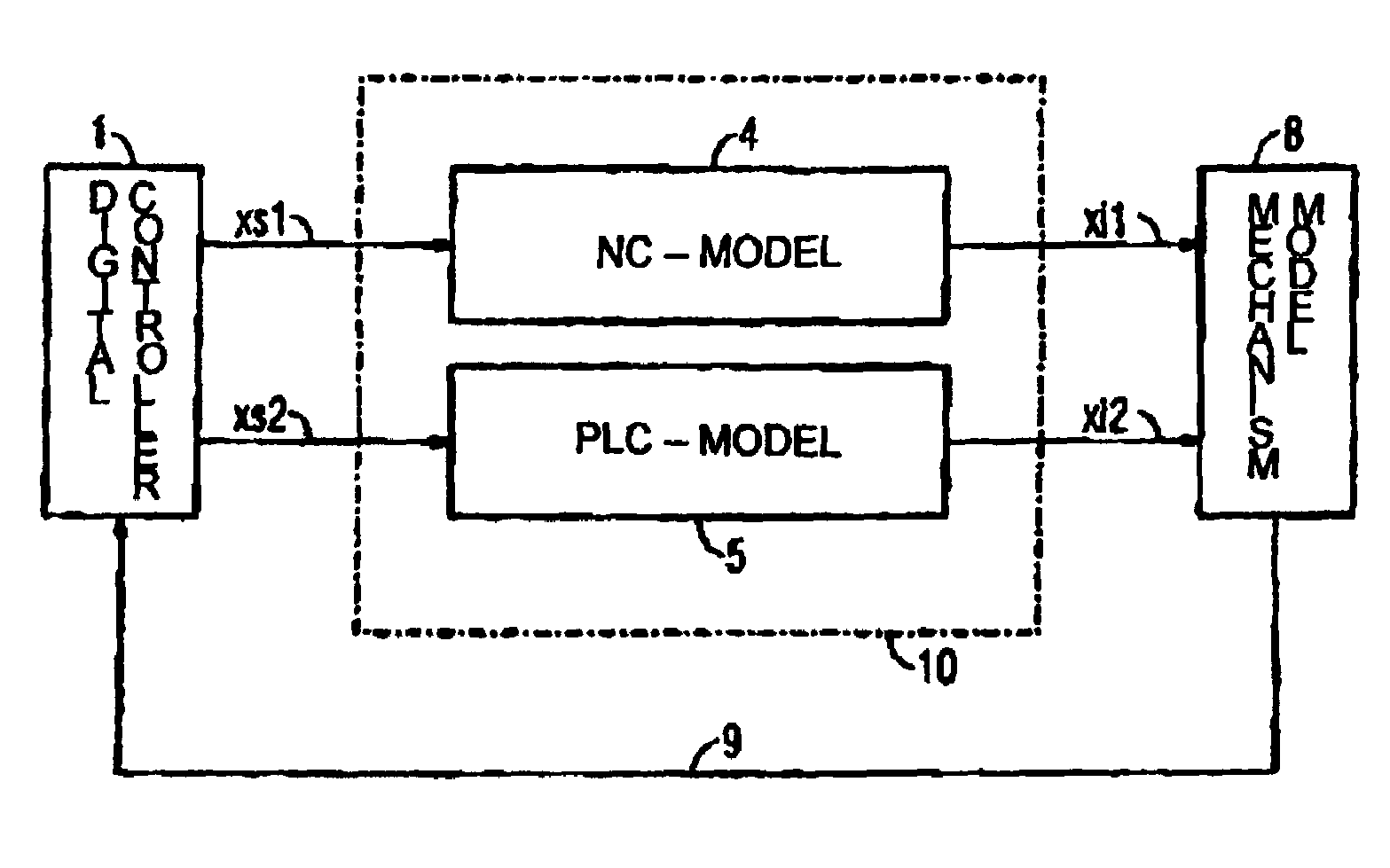
[0033]Turning now to the drawing, and in particular to FIG. 1, there is shown a schematic block diagram of a simulation in accordance with the invention, including a digital controller 1, which outputs a desired NC-axis value “xs1” for each numerically-controlled (NC) axis to a related NC-model and outputs a desired PLC-axis value “xs2” for each programmable-logic controlled (...


PUM


Abstract

An apparatus and method for simulating the behavior of the drive system and the mechanism of machine tool or production-line machine by use of mathematical models of the drives and the mechanisms of the driven mechanical elements of the machine are disclosed. Preferably actual values for regulated and unregulated axes are calculated at the same time using NC- and PLC-models, respectively by an auxiliary computer using desired values provided by a digital controller. The actual values are then supplied to a mechanism model, preferably a geometric kinematic model, which produces a state signal that is fed back to the digital controller, preferably in real time. The result is an efficient, easy and cost-effective simulation that closely approximates reality and can be provided in real-time.

Description

CROSS-REFERENCES TO RELATED APPLICATIONS[0001]This application claims the priority of German Patent Application, Serial No. 102 48 991.2, filed Oct. 21, 2002, pursuant to 35 U.S.C. 119(a)–(d), the disclosure of which is incorporated herein by reference.BACKGROUND OF THE INVENTION[0002]The present invention relates to a method and apparatus by which the actual parameters of a machine's operations can be calculated from theoretical values with the help of models of the drive systems and of the mechanism of the machine.[0003]With the increasing product-quality and economic-efficiency requirements being placed on machine-tool and production-line machine, including robots, the complexity of these machines is constantly increasing. Novel machine kinematics and complex mechanical-electronic functions require greater functional efficiency in the mechanism, drivers and control. However, this is not always easy to design and implement. Because the increasingly urgent need to know the producti...

Claims


Application Information

Patent Timeline
Patent Type & Authority Patents(United States)
IPC IPC(8): G06F17/10G05B13/02G05B17/02G05B19/4069
CPCG05B17/02G05B19/4069G05B2219/34391G05B2219/33324G05B2219/32342Y02P90/02
Inventor DOLANSKY, STEFANMENZEL, THOMASPAPIERNIK, WOLFGANG
Owner SIEMENS AG
Why Eureka
Try Eureka