High temperature and pressure testing facility

a high temperature and pressure testing and testing facility technology, applied in the direction of gas turbine engine testing, structural/machine measurement, instruments, etc., can solve the problems of significant and costly damage, high cost of testing advanced components, materials, coatings, etc., and the use of special test engines is extremely expensiv

Active Publication Date: 2007-02-13
FLORIDA TURBINE TECH
View PDF9 Cites 18 Cited by
  • Summary
  • Abstract
  • Description
  • Claims
  • Application Information

AI Technical Summary

Problems solved by technology

Testing of advanced components, materials, and coatings under extreme conditions that directly simulate engine operation is very costly.
Use of a special test engine is extremely expensive.
Therefore a low-cost testing facility is needed that can test this hardware during the experimental, high risk phase of development, and where failure to the test article does not have the potential to cause significant and costly damage to the test facility.
However, even this approach results in high costs due to uncertainty of the test article's performance, life, and potential for destructive failure, and the resulting impact on power plant's repairs, operability, and availability.
While these burner tests are more easily accomplished than full engine testing they exclude some of the effects that induce material and / or coating failures like thermal mechanical failure in the base metal, coating spallation due to high thermal gradients, erosion due to high velocity flow, corrosion degradation due to trace elements in fuel at operating temperatures and pressures, ability to apply mechanical loads, and radiation loads in the combustor.
There are additional testing problems associated with testing hardware intended for advanced engines that are yet to be developed.
In this case, existing engines cannot provide the operating temperatures and pressures that this hardware will endure in the advanced engine.

Method used


Image

  • High temperature and pressure testing facility
  • High temperature and pressure testing facility
  • High temperature and pressure testing facility

Examples


first embodiment

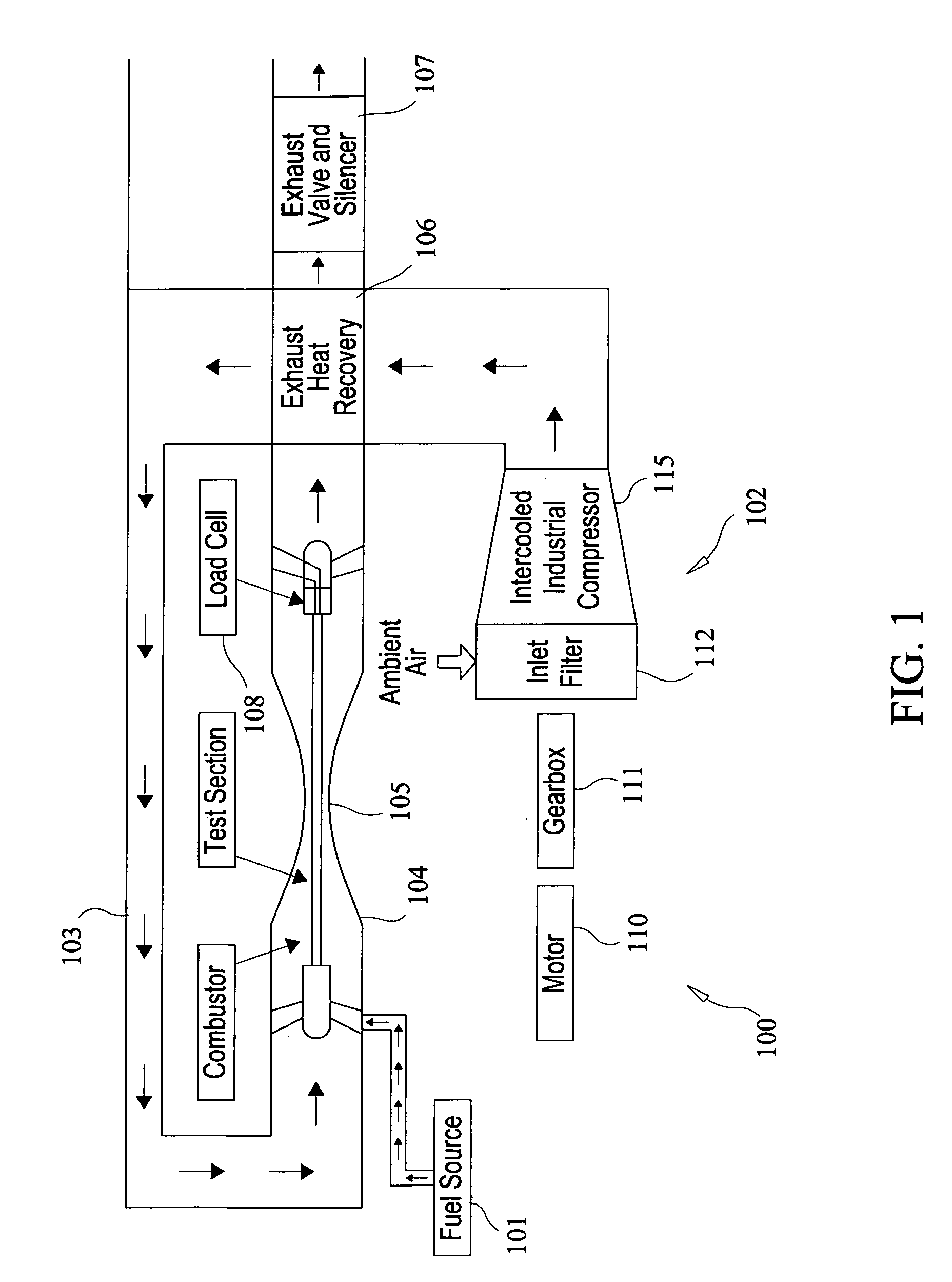
[0027]After combustion, the flow is accelerated into the test section 105 of the facility, which, in the present invention, may include a cooled inner conduit or pipe within an outer pipe or sleeve. The inner pipe may have test material coupons or coatings (not shown) deposited or fixed on its outer surface, which may be loaded using the load cell 108 to evaluate both steady-state and transient loads (such as vibration or pull loads). Realistic thermal gradients through the test samples are accomplished in the test section 105 by simulating engine hot gas path conditions on one side of the inner pipe, and cooling side heat transfer on the other side. The test article may also be film cooled if desired. The load cell 108 controls are located outside the test section 105 housing. For each of the combustor 104, test section 105, and high temperature downstream parts, a combination of convective and film cooling is used to maintain material operating temperatures within acceptable limit...

second embodiment

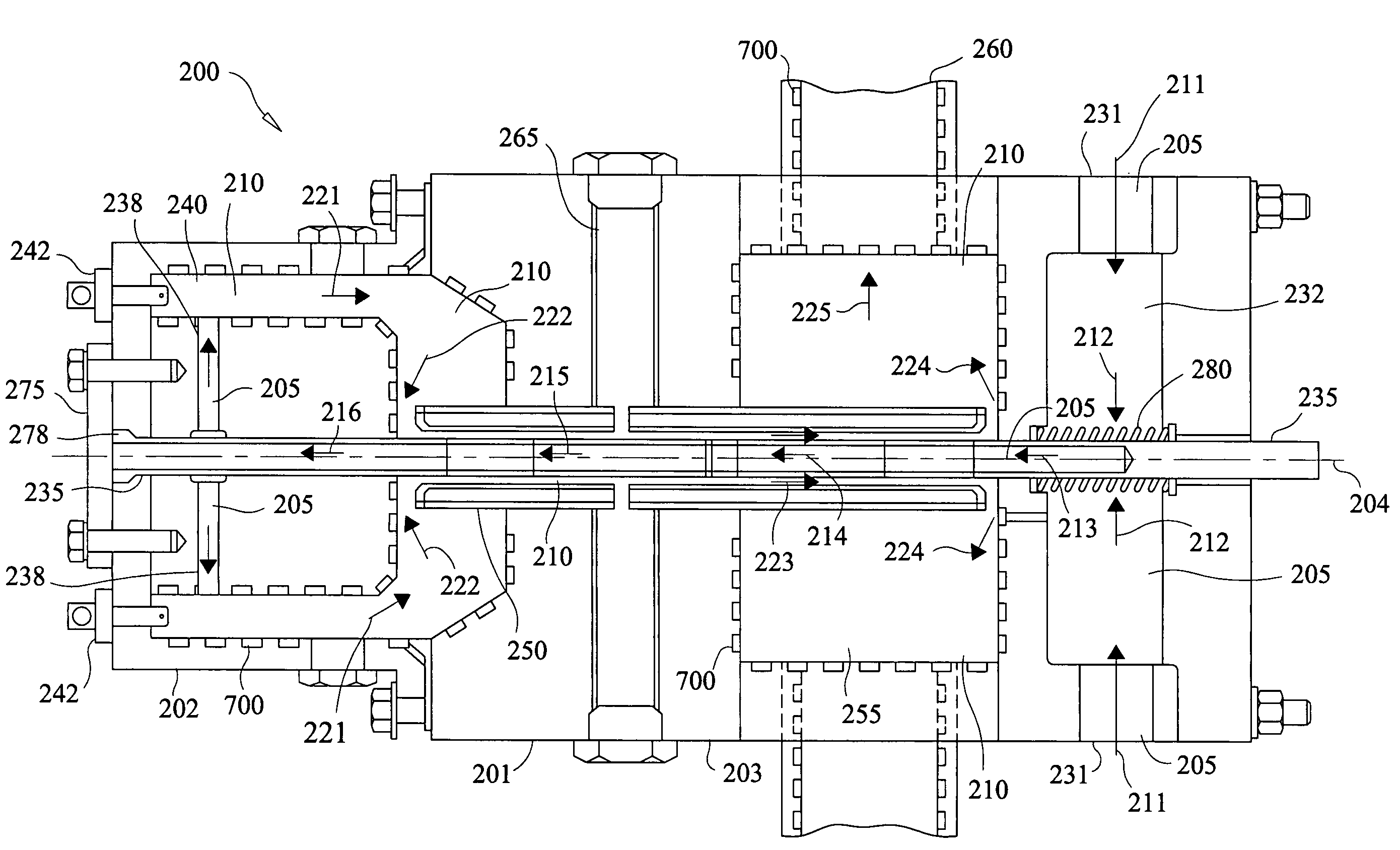
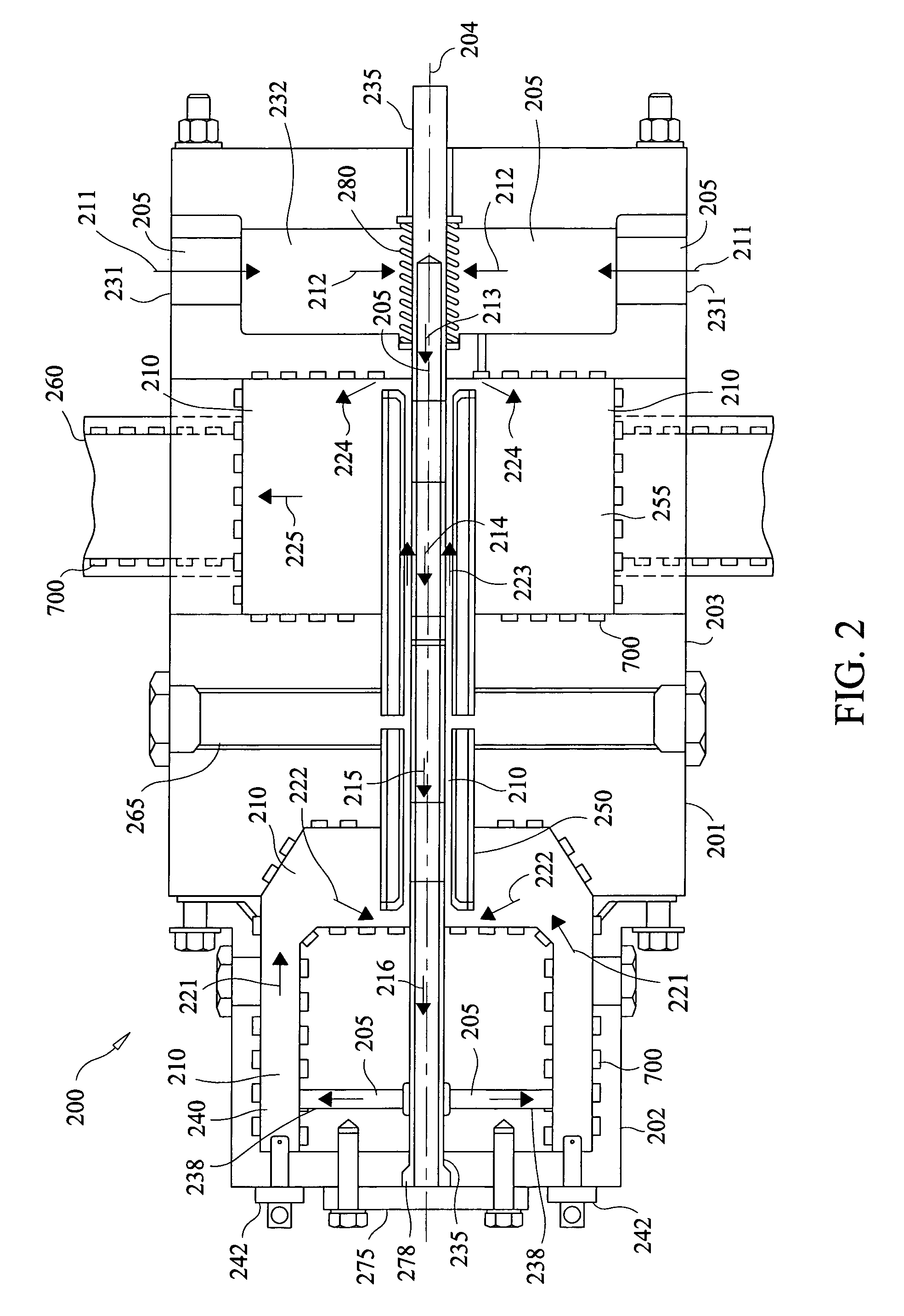
[0042]FIG. 4 is a longitudinal cross-sectional view of a test section 400 incorporated into a test facility of the present invention, such as the overall test facility described in FIG. 1. In this embodiment, test section 400 includes a housing 401, which includes both a combustor section 402 and a central test section 403. As with the previous embodiment shown in FIG. 2, the combustor section 402 is therefore incorporated into the overall test section 400, and is included in the same housing 401 which includes the main central test section 403. Alternatively, the combustor section 402 may be separate from the central test section 403, and may not be included in a single integrated housing, but may be separable or removable from the central test section 403. The test section housing 401 is substantially axisymmetric about a central longitudinal axis 404; such that the chambers and passages defined therein may be annular bodies of revolution about the central axis 404.

[0043]The test ...


PUM

PropertyMeasurementUnit
temperatureaaaaaaaaaa
pressuresaaaaaaaaaa
pressureaaaaaaaaaa

Abstract

A test facility is provided for testing materials under high temperature, pressure, and mechanical loads. The facility provides a physically scaled system that simulates conditions in hot sections of gas turbine engines. A test article is coated with a test material and exposed to a hot combusting flow in a test section housing. The article may be a pipe or conduit member oriented at any direction to the flow. A second cooler flow of fluid is channeled through the test article to create a sharp temperature gradient in the test article and through the test material. A liquid-cooled sleeve is disposed about the test article to create an annular channel of combusting flow over the test article. The downstream end of the second cooler flow is connected to the upstream end of the main hot flow at the combustion chamber.

Description

CROSS-REFERENCE TO RELATED APPLICATION[0001]This application is related to and claims priority to U.S. Provisional Patent Application Ser. No. 60 / 418,549, filed Oct. 15, 2002, entitled HIGH TEMPERATURE AND PRESSURE TESTING FACILITY, and U.S. Provisional Patent Application Ser. No. 60 / 482,560, filed Jun. 25, 2003, entitled HIGH TEMPERATURE AND PRESSURE TESTING FACILITY, the entirety of which is incorporated herein by reference.STATEMENT REGARDING FEDERALLY SPONSORED RESEARCH OR DEVELOPMENT[0002]n / aFIELD OF THE INVENTION[0003]The present invention relates to a system and method for testing materials in high temperature and pressure environments, thereby simulating the conditions in a gas turbine engine.BACKGROUND OF THE INVENTION[0004]Testing of advanced components, materials, and coatings under extreme conditions that directly simulate engine operation is very costly. In most cases it involves the installation of the test article(s) in a special test engine in the case of aircraft en...

Claims


Application Information

Patent Timeline
Patent Type & Authority Patents(United States)
IPC IPC(8): G01N33/00G01M15/14G01M99/00G01N3/00G01N3/02G01N3/18G01N17/00
CPCG01M15/14G01M99/002G01N3/18G01N17/002G01N25/00G01N2203/0232G01N2203/0042G01N2203/0057G01N2203/0226
Inventor BROSTMEYER, JOSEPHWILSON, JACKEBERT, TODD A.
Owner FLORIDA TURBINE TECH
Why Eureka
Try Eureka