Muffler for internal combustion engine

a technology for internal combustion engines and mufflers, which is applied in the field of mufflers, can solve the problems of increasing the risk of fire, releasing extreme heat from the muffler, and getting a relatively short life, so as to improve the cooling effect, improve the safety, and improve the effect of mufflers

Inactive Publication Date: 2007-02-13
HUSQVARNA AB
View PDF26 Cites 26 Cited by
  • Summary
  • Abstract
  • Description
  • Claims
  • Application Information

AI Technical Summary

Benefits of technology

[0013]A spark-arrester screen can be arranged between the inner outlet of the muffler and the outlet duct for arresting sparks brought by the exhaust gases. The spark-arrester screen can also be arranged in the outlet duct or at the very exhaust outlet. Thereby a combination of spark-arrester and outlet labyrinth is achieved, thus providing a satisfactory elimination of both sparks and flaming.
[0014]The outlet duct is preferably orientated in parallel with the outer wall of the muffler housing. This orientation is advantageous from considerations of space as well as for the functioning of the outlet duct. The cooling can be improved in that the outlet duct is located at the same level as the outside of the muffler. Furthermore, since the first section is orientated along the muffler housing a relatively substantial change of the flow direction will occur already when the exhaust gases are arriving at the first section. The change of direction between the first and the second section will thereby become even more effective. For the same reason it is particularly preferable that the second section is located outside the first section counted from the housing, so that the sections are located outside each other.
[0015]According to a preferred embodiment the first section is embodied of a first curved, elongated baffle (duct) having an end-gable located at the inner outlet and an aperture located at a distance from this, and the second section is embodied of a second curved baffle having an end-gable located at said aperture, and a mouth located along the first baffle, whereby the second section is embodied of a space created in between said first and second baffles. The labyrinth, which is created in this manner has been found to function satisfactory, and both parts can easily be mounted tight to the muffler housing. Both baffles can easily be adapted considering curving and length in order to achieve an optimal outlet labyrinth.

Problems solved by technology

The compact design of the above-mentioned type of catalytic muffler results in that the exhaust gases will leave the muffler relatively soon after they have passed through the catalytic converter, and thus extremely hot exhaust gases are released from the muffler.
This could lead to an increased risk of fire, particularly since this type of smaller engines are often used in tools handled in fire risk environments with plenty of inflammable material.
For obtaining a satisfactory result the spark-arrester screen must be so fine-meshed that it gets a relatively short lifetime.
However, such a spark-arrester screen can only to a limited extent put out flames.

Method used


Image

  • Muffler for internal combustion engine
  • Muffler for internal combustion engine
  • Muffler for internal combustion engine

Examples


Embodiment Construction

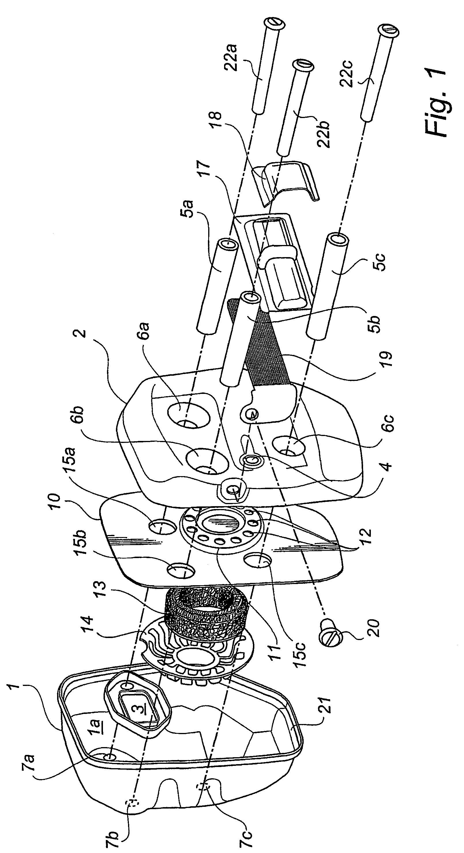
[0024]The catalytic muffler shown in FIG. 1 in an exploded view is in itself of a known type, however equipped with an outlet duct according to an embodiment of the invention. The muffler comprises a housing 1, 2 consisting of a housing 1 and a lid 2, preferably made from a thin metal sheet or another material with similar characteristic features. The housing 1 is intended to be mounted to an exhaust outlet of an engine cylinder (not shown), and has therefore an inlet 3, while the lid 2 has an inner outlet 4 for the exhaust gases cleaned by the catalytic converter. Distance elements 5a–c are arranged between the housing 1 and the lid 2, and are intended to penetrate through for the purpose configured apertures 6a–c in the lid 2 and to support against the rear wall of the housing 1 around apertures 7a–c.

[0025]Between the housing 1 and the lid 2 an intermediate wall 10 is arranged, having an annular area 11 with apertures 12, at which an annular catalytic converter element 13 is inte...


PUM


Abstract

The subject invention refers to a muffler comprising a muffler housing (1, 2) and generally a catalytic converter element (13) mounted in the housing, which muffler has at least one inner outlet (4) through which exhaust gases cleaned by the catalytic element (13) are intended to pass. Furthermore, according to the invention an outlet duct (30, 31) is arranged in connection to the outside of the housing, comprising a first section (30) for leading exhaust gases in a first direction (A) in parallel with the outside of the housing, and a second section (31) for leading exhaust gases in a second, opposite direction (B), whereby said first and second sections (30, 31) have an essentially equally large cross-sectional area. By way of this outlet duct an improved cooling of the exhaust gases before they are brought in contact with fresh air rich in oxygen can be achieved. A back-pulsation of fresh air into the muffler can also be prevented.

Description

[0001]This application claims the benefit of International Application Number PCT / SE00 / 02158, which was published in English on May 10, 2002.TECHNICAL FIELD[0002]The subject invention refers to a muffler comprising a muffler housing and generally a catalytic converter element mounted in the housing, said muffler has at least one inner outlet through which exhaust gases are intended to pass.BACKGROUND OF THE INVENTION[0003]Cleaning of exhaust gases by using catalytic converters has nowadays become more and more common even in smaller internal combustion engines of two-stroke type, e.g. in handheld power-driven working tools, such as chain saws and grass trimmers. Demands concerning weight and size of the exhaust cleaning equipment have led to the development of so called catalytic mufflers which are mounted directly to the exhaust port of the cylinder. A typical catalytic muffler has a sealed housing with an inlet as well as an outlet port, and a catalytic element mounted in the hous...

Claims


Application Information

Patent Timeline
Patent Type & Authority Patents(United States)
IPC IPC(8): F01N3/02F01N3/06F01N1/08F01N7/08F01N3/24F01N3/28F01N13/08F02B63/00F02B75/02
CPCF01N1/084F01N3/06F01N13/082F02B63/00F01N3/2885F02B2075/025
Inventor GUNNARSSON, PETEROLLAS, ESBJORNOSSIANSSON, MATTIAS
Owner HUSQVARNA AB
Why Eureka
Try Eureka