Air staged low-NOx burner

a low-nox burner and burner technology, applied in the field of low-nox burners, can solve the problems of limiting flame temperature and thermal nox, and achieve the effects of reducing nox production, limiting flame temperature and thermal nox, and reducing nox emissions

Inactive Publication Date: 2007-02-13
BLOOM ENG
View PDF68 Cites 82 Cited by
  • Summary
  • Abstract
  • Description
  • Claims
  • Application Information

AI Technical Summary

Benefits of technology

[0007]The present invention uses staged air combustion to reduce the production of NOx from a burner and includes a burner body adjacent a port block. The present invention also includes a fuel passageway connecting a fuel source to a burner throat. Primary air jets are connected to an air source and inject air into a primary combustion region. This primary combustion region is in the burner throat. The primary air jets can be configured such that air is introduced into the primary combustion region in a swirling manner. A dish surface is located in the port block; the dish surface extending in an angle divergent with respect to a centerline extending through the burner throat. Finally, the present invention utilizes secondary air jets connected to an air source. These secondary air jets extend through the port block and inject secondary air into a secondary combustion region located downstream from the primary combustion region.
[0008]The present invention also includes a method of reducing NOx emissions from a burner, wherein fuel is taken from a fuel source and injected into a burner throat via a fuel passageway, and primary air is injected from an air source into a primary combustion region in the burner throat. Further, this primary combustion is conducted in a fuel-rich highly vitiated environment which consumes available oxygen, limiting flame temperature and thermal NOx. Fuel is fed into the burner and proceeds to the throat where the primary air and fuel mix together to form the initial stage of combustion. A combustion reaction is initiated in the burner throat. The preferable convergent, angled introduction of the air through the primary air jets creates a swirling cyclone pattern that hugs the walls of the port block and pulls and mixes the fuel and recirculated products of combustion into the cyclone. After the primary combustion step, the air / fuel mixture then enters a secondary combustion region. Air is introduced into the secondary combustion region so as to allow the combustion process to complete. Products of combustion are drawn into a vortex created by the swirling mixture of fuel and air during the combustion process. The overall NOx production is thereby reduced.

Problems solved by technology

Further, this primary combustion is conducted in a fuel-rich highly vitiated environment which consumes available oxygen, limiting flame temperature and thermal NOx.

Method used


Image

  • Air staged low-NOx burner
  • Air staged low-NOx burner
  • Air staged low-NOx burner

Examples


Embodiment Construction

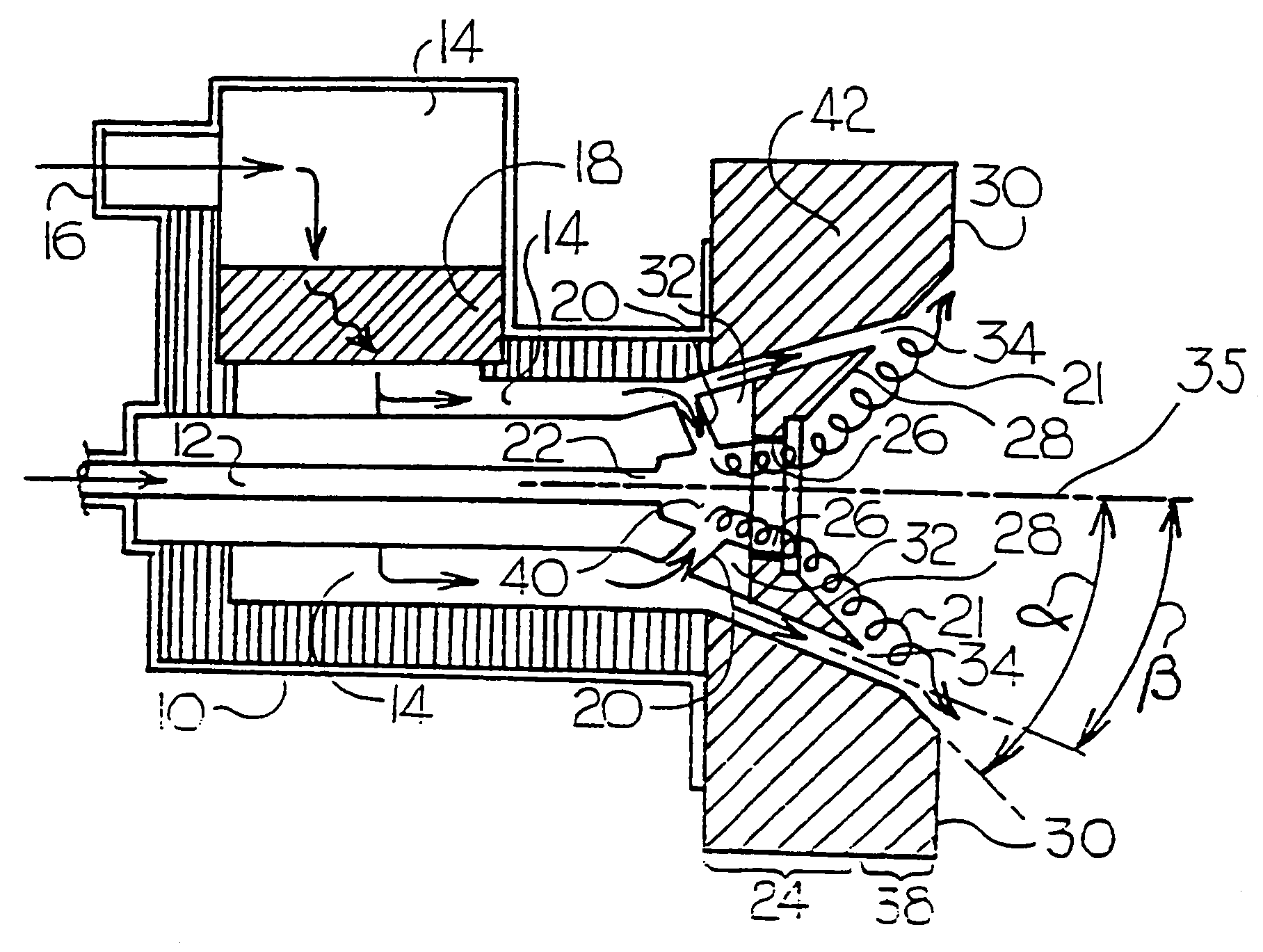
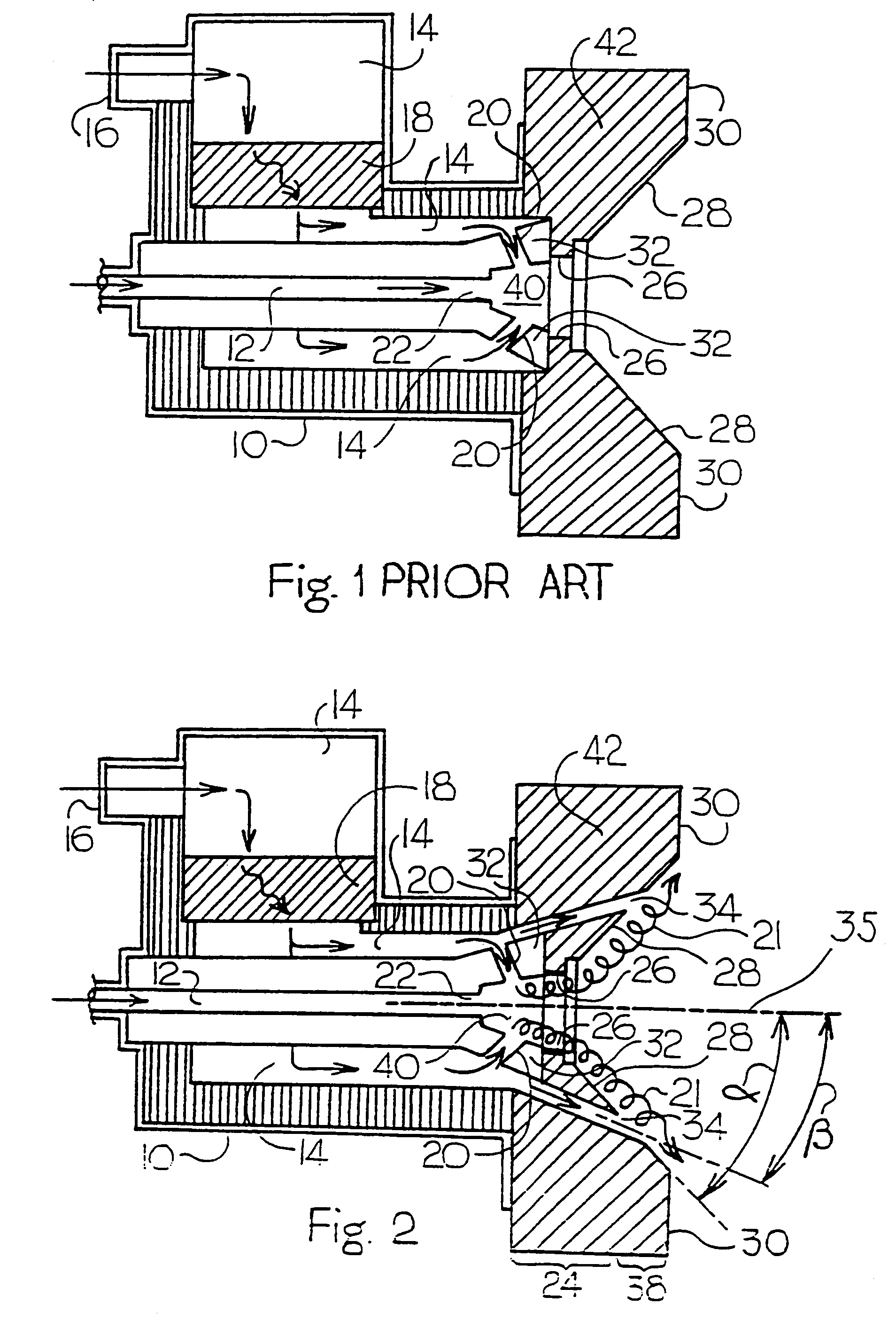
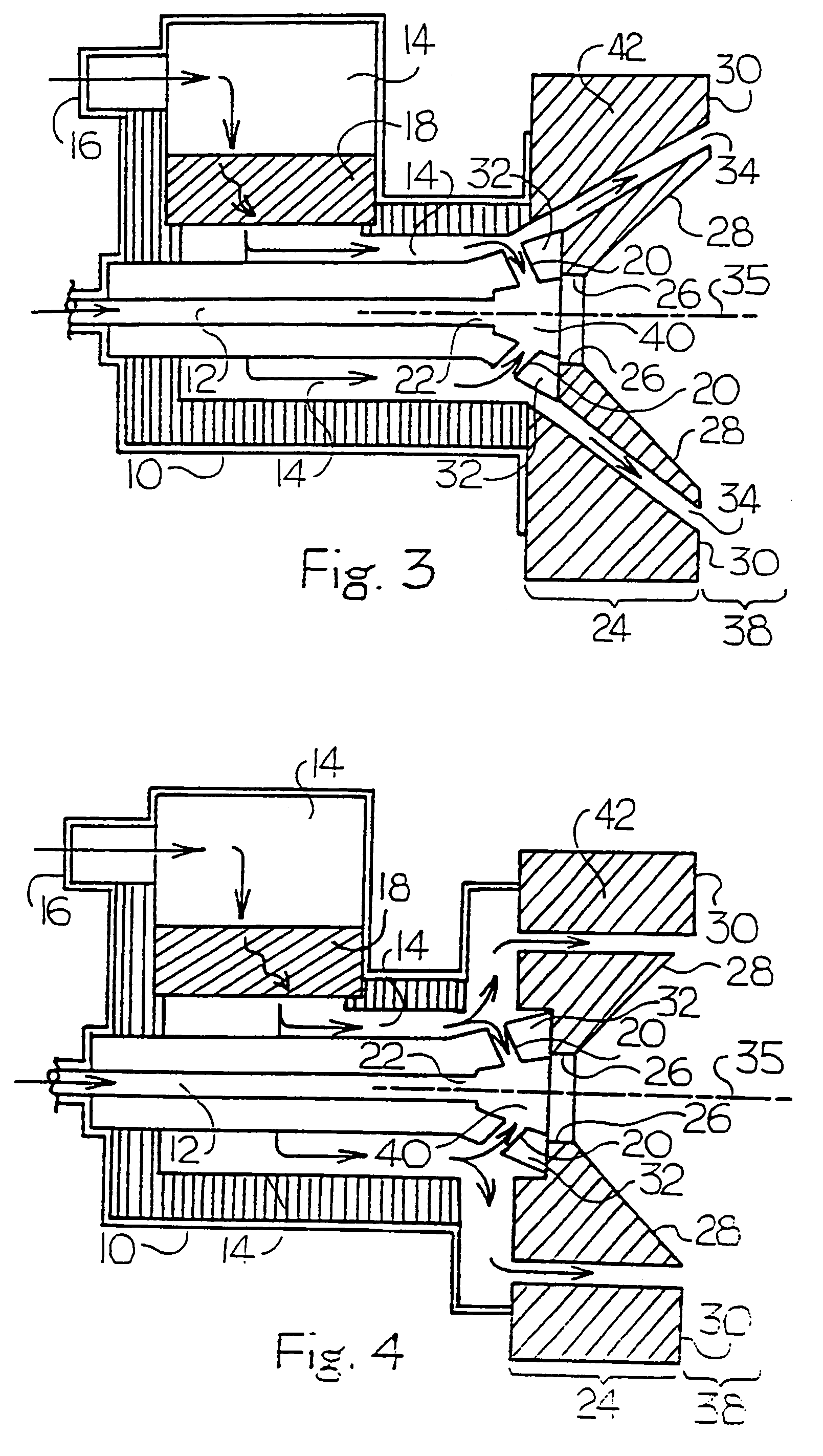
[0021]As seen in FIG. 1, the design of a typical prior art burner includes a burner body 10, which houses an air passageway 14 and a fuel passageway 12. The air passageway 14 may have an optional heat storing media 18 area, depending upon the application. Fuel is introduced into the fuel passageway 12, which directs the fuel through the burner body 10, and flows out through a fuel nozzle 22. All required combustion air enters through an air entrance 16, runs through the air passageway 14 and enters a combustion region through primary air jets 20. The burner body 10 is fixed to a port block 42. The fuel and air initially mix in a burner throat 40 of the burner. Combustion occurs in the burner throat 40 and continues into cup 26 and from these to a space surrounded by a dish surface 28.

[0022]The present invention is an apparatus and method directed to an air-staged low-NOx burner. The first embodiment is illustrated in FIG. 2. A liquid or gaseous fuel is introduced into the burner bod...


PUM


Abstract

An apparatus and method for using staged air combustion. The apparatus includes a burner body (10) secured to a port block (42), and a fuel passageway (12) extending through the burner body (10), terminating in a fuel nozzle (22), which injects fuel into the burner throat (40). Primary air jets (20) are configured to inject primary air into a primary combustion region (24), which is normally in the burner throat (40). A dish with a dish surface (28) is connected to the burner throat (40); the dish surface (28) extending in a divergent angle with respect to a burner centerline (35). Secondary air jets (34) are connected to the air passageway (14) and extend through the port block (42). The secondary air jets (34) inject secondary air into a secondary combustion region (38), which may be at the dish surface (28) or the hot face (30) of the burner.

Description

BACKGROUND OF THE INVENTION[0001]1. Field of the Invention[0002]The present invention relates to low-NOx burners, and, in particular, to air-staged low-NOx burners.[0003]2. Description of the Prior Art[0004]Oxides of nitrogen (NOx) are produced from the burning of fuels during the normal operation of a typical burner. These oxides combine with hydrocarbons in the atmosphere, creating “smog”, which, when inhaled, may cause injury. Further, the U.S. Environmental Protection Agency, as well as state and local air pollution agencies, have passed certain environmental laws providing limitations and technological standards on the amount of NOx a facility may emit. These standards are continuing to become more and more stringent, creating a technological need for low-NOx burners.[0005]Decreasing the NOx emissions from a burner is a well-known need. For example, U.S. Pat. No. 4,004,875 to Zink et al. (hereinafter “the Zink patent”) discloses a low-NOx burner concept that introduces secondar...

Claims


Application Information

Patent Timeline
Patent Type & Authority Patents(United States)
IPC IPC(8): F23D14/22F23C7/00F23C7/02F23C99/00
CPCF23C6/045F23C7/002F23D14/66F23D17/002F23D14/24F23C2900/06043F23D2900/11101Y02E20/34
Inventor PISANO, STEPHEN P.FENNELL, ANTHONY G.HEMMERLIN, JOHN R.BAGGLEY, GLENN W.DORMIRE, JOHN C.
Owner BLOOM ENG
Why Eureka
Try Eureka