Diesel engine exhaust purifier

a technology for diesel engines and purifiers, which is applied in mechanical devices, electric control, machines/engines, etc., can solve the problems of less nox generated, accelerate the combustion of soot, reduce the temperature of exhaust gas, and reduce the amount of nox generated

Inactive Publication Date: 2010-10-21
LENZ ENVIRONMENTAL RESOURCES
View PDF0 Cites 11 Cited by
  • Summary
  • Abstract
  • Description
  • Claims
  • Application Information

AI Technical Summary

Benefits of technology

[0008]In the control of the water ratio, the basic water ratio is set up such that, during normal driving, the water ratio in the engine operational range having a large acceleration pedal depression amount is increased compared with that having a small accelerator pedal depression amount. Accordingly, since the combustion temperature is lowered due to the existence of the water, it is possible to reduce the generation of NOx. In this case, since the water ratio is controlled as described above, it is always possible to allow the exhaust emission control efficiency and engine power performance to be consistent with each other even in a broad engine operational range like the case of vehicles.
[0035]In the case when there is a possibility that the catalyst or filter may be damaged due to extraordinary high temperatures of the exhaust gas in a diesel particulate filter, it is possible to reduce the temperature of the exhaust gas by increasing the water ratio to prevent the above filter from overheating. Conversely, to accelerate the combustion of the soot or the like while the temperature in the filter is low, it is possible to raise the temperature in the filter easily and swiftly by reducing the water ratio to raise the temperature of the exhaust gas.

Problems solved by technology

However, since the above period of the operation is short and the engine speed decreases because of the large load, the amount of the generated NOx becomes less than that generated during normal driving.

Method used


Image

  • Diesel engine exhaust purifier
  • Diesel engine exhaust purifier
  • Diesel engine exhaust purifier

Examples


first embodiment

[0068]Next, the working of the exhaust emission control apparatus for diesel engines which has the above-described constitution, will be described.

[0069]First of all, to start the engine, the starter switch is turned ON to rotate the starter (not shown) to give turning force to the diesel engine 2.

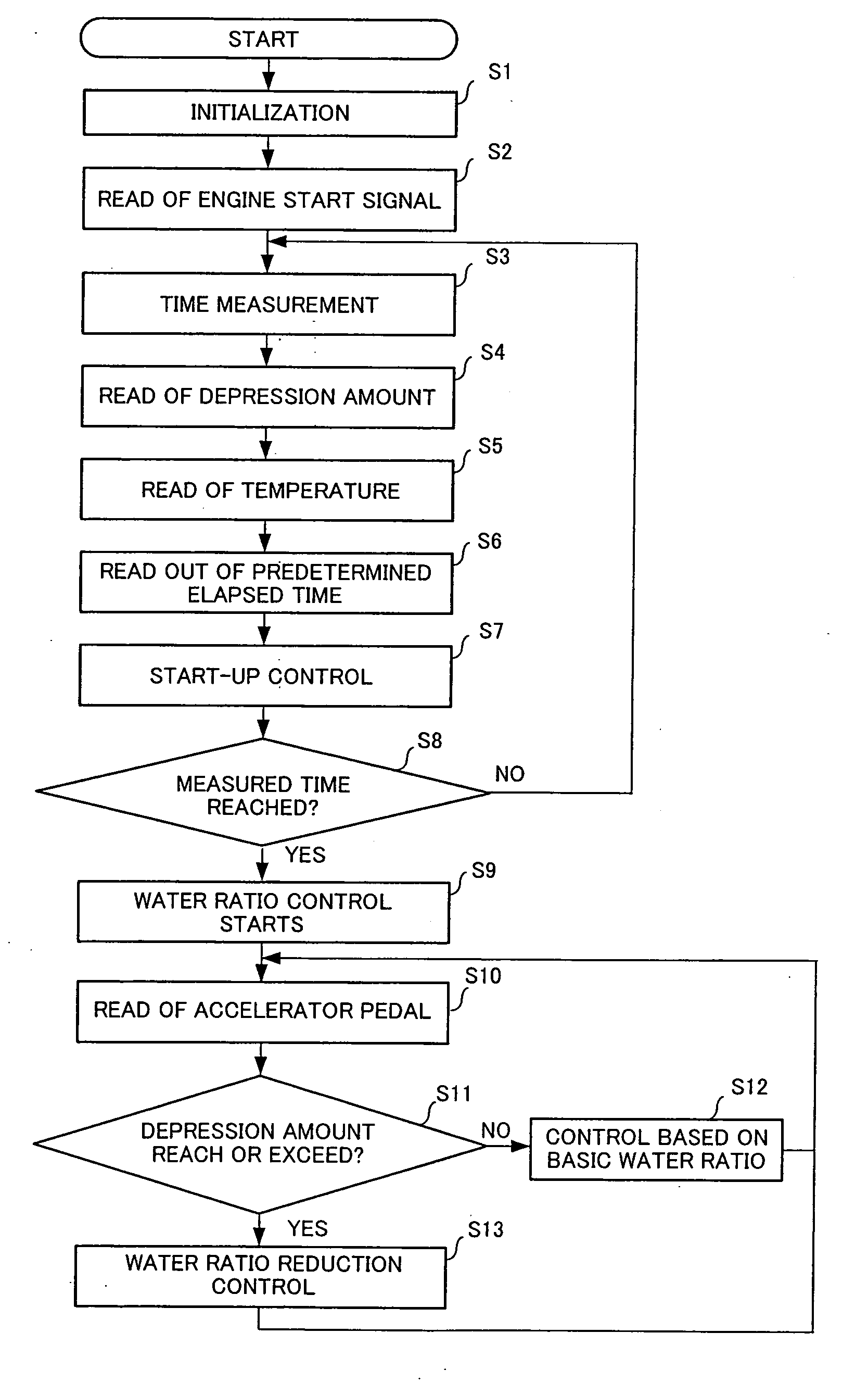
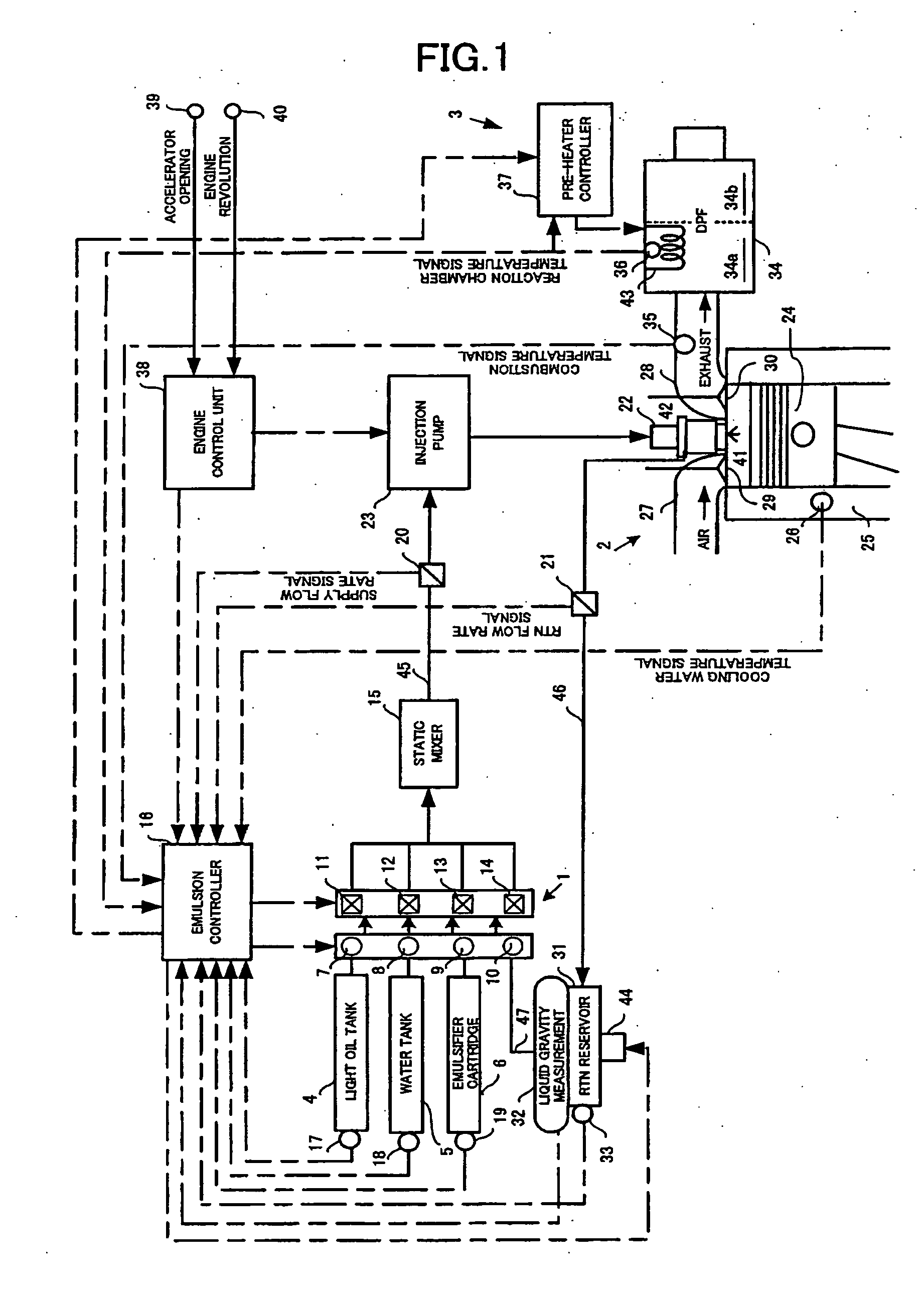
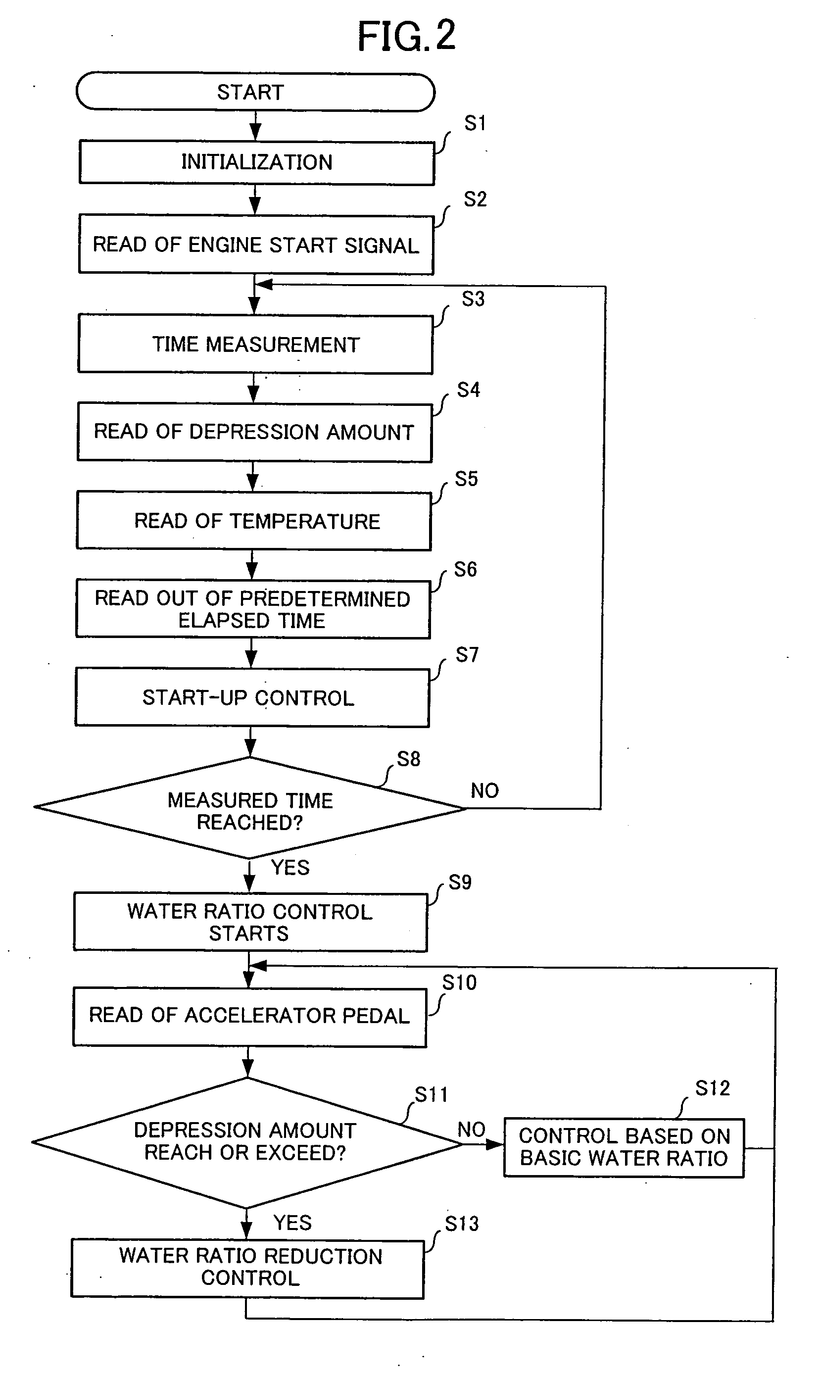
[0070]Accompanying the engine start, the emulsion controller 16 judges the engine is the starting by detecting the ON-actuation of the starter switch. The emulsion controller 16 receives oxidation catalyst reaction temperature signal from the reaction chamber temperature sensor 36, exhaust gas temperature signal from the combustion temperature sensor 35, flow rate signal of the emulsified fuel from the supply flow rate sensor 20, flow rate signal of the returned fuel from the return flow rate sensor 21, residual signal and the like from each residual sensors 17, 18, 19 and 33 and starts to generate and supply the emulsified fuel having an optimum water ratio.

[0071]As shown in a control fl...

second embodiment

[0092]Then, an exhaust emission control apparatus for diesel engines according to the invention will be described below.

[0093]FIG. 3 shows a constitution of a power train in the second embodiment. In FIG. 3, the substantially same items as those in FIG. 1 will be given with the same reference symbols as those in FIG. 1; and the descriptions thereof will be omitted.

[0094]A non-driving wheel (not shown) is provided with a wheel speed sensor 48 for detecting wheel speed to send a signal about the wheel speed to the emulsion controller 16. And in the return path 46 connecting between the fuel injection valve 22 and the return reservoir 31, a return temperature sensor 47 is provided to send a signal about the temperature of the returned fuel to the emulsion controller 16. The other constitution is substantially the same as that in FIG. 1.

[0095]The exhaust emission control apparatus for diesel engines having the above constitution is controlled in accordance with a control flow chart as d...


PUM


Abstract

An exhaust emission control apparatus for diesel engines is offered which is capable of achieving better power performance and exhaust emission purification efficiency in an optimally reconciled manner, and from which torque deficiency during hill climbing on a steep slope is eliminated. Emulsified fuel including light oil, water and emulsifier supplied respectively from a light oil tank 4, a water tank 5 and an emulsifier cartridge 6, of which the water ratio is adjusted by flow variable control valves 11-13, is supplied to a combustion chamber 4. The water ratio is normally set to a basic water ratio corresponding to the signal of an accelerator opening sensor 39 (Step S32). However, when a difference between target acceleration and actual acceleration of a vehicle corresponding to the accelerator pedal opening exceeds a predetermined value (Step S36), the basic water ratio is corrected so as to reduce the water ratio (Step S37).

Description

BACKGROUND OF THE INVENTION[0001]The present invention relates to an exhaust emission control apparatus for diesel engines adapted to suppress particularly the generation of nitrogen oxides in the exhaust gas.[0002]As for a conventional exhaust emission control apparatus for diesel engines, a technique in which water and emulsifier are added to fuel and supplied to a combustion chamber as emulsified fuel to lower the highest combustion temperature in the combustion chamber whereby generation of nitrogen oxides are suppressed is known from the description in Japanese Laid-Open Patent Application (Kokai) (A) No. Heisei 7-166962 (1995) titled “ENGINE EMULSIFIED FUEL FEEDER UNIT” and Japanese Laid-Open Patent Application (Kokai) (A) No. Heisei 7-166963 (1995) titled “ENGINE EMULSIFIED FUEL FEEDER UNIT.”[0003]In the above official gazettes, it is surely described that the ratio of adding water (water ratio) to the fuel is decided depending on the state of load on the engine. However, the...

Claims


Application Information

Patent Timeline
Patent Type & Authority Applications(United States)
IPC IPC(8): F02B47/02F01N3/023F02D19/12
CPCF01N3/027F01N3/106F01N3/2013F02D19/12F02D41/0025F02M25/03F02M43/00Y02T10/26F02M25/0227F02M25/0228F02D41/10Y02T10/12Y02A50/20
Inventor SAKURAI, SHINICHIROSHINODA, SATORU
Owner LENZ ENVIRONMENTAL RESOURCES
Why Eureka
Try Eureka