Light emitting apparatus and method for curing inks, coatings and adhesives

Inactive Publication Date: 2007-02-13
CON TROL CURE
View PDF71 Cites 79 Cited by
  • Summary
  • Abstract
  • Description
  • Claims
  • Application Information

AI Technical Summary

Benefits of technology

[0009]As will be described in greater detail hereinafter, the method and device of the present invention provide techniques and structures for applying UV light emitted from UV-LED's mor

Problems solved by technology

While the use of a large number of UV-LED's provide many efficiencies, namely in cost and energy consumption, there is still the problem of effective curing with l

Method used


Image

  • Light emitting apparatus and method for curing inks, coatings and adhesives
  • Light emitting apparatus and method for curing inks, coatings and adhesives
  • Light emitting apparatus and method for curing inks, coatings and adhesives

Examples


Embodiment Construction

[0031]A detailed description of the preferred embodiments and best modes for practicing the invention are described herein.

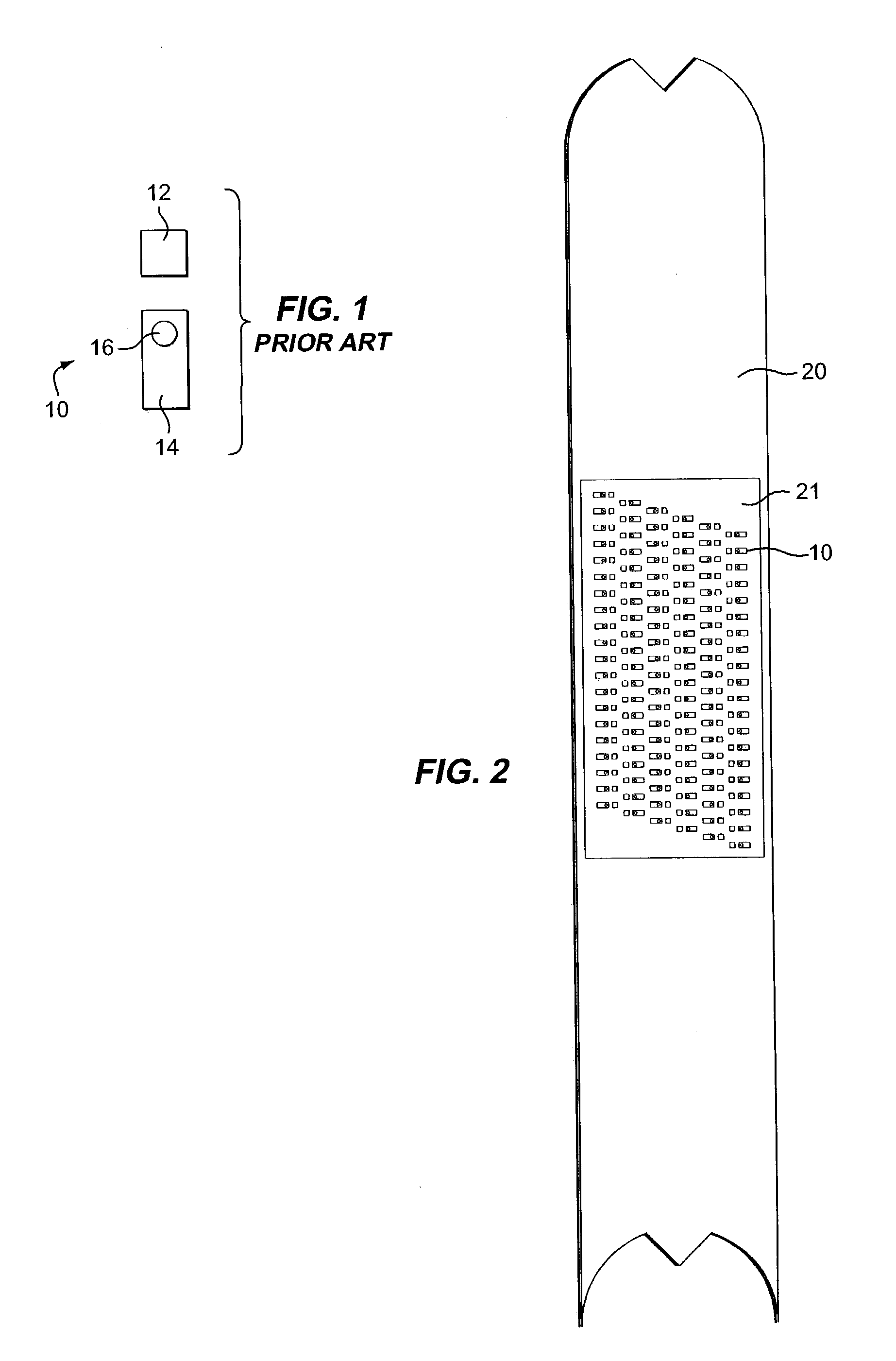
[0032]Referring now to the drawings in greater detail, there is illustrated in FIG. 1 a prior art ultraviolet light-emitting diode (UV LED) assembly 10 including a cathode pad 12 and an anode 14 mounting a chip 16, which comprises a UV LED chip 16.

[0033]Each cathode pad 12 (FIG. 1) is connected to a wire conductor as is each anode 14.

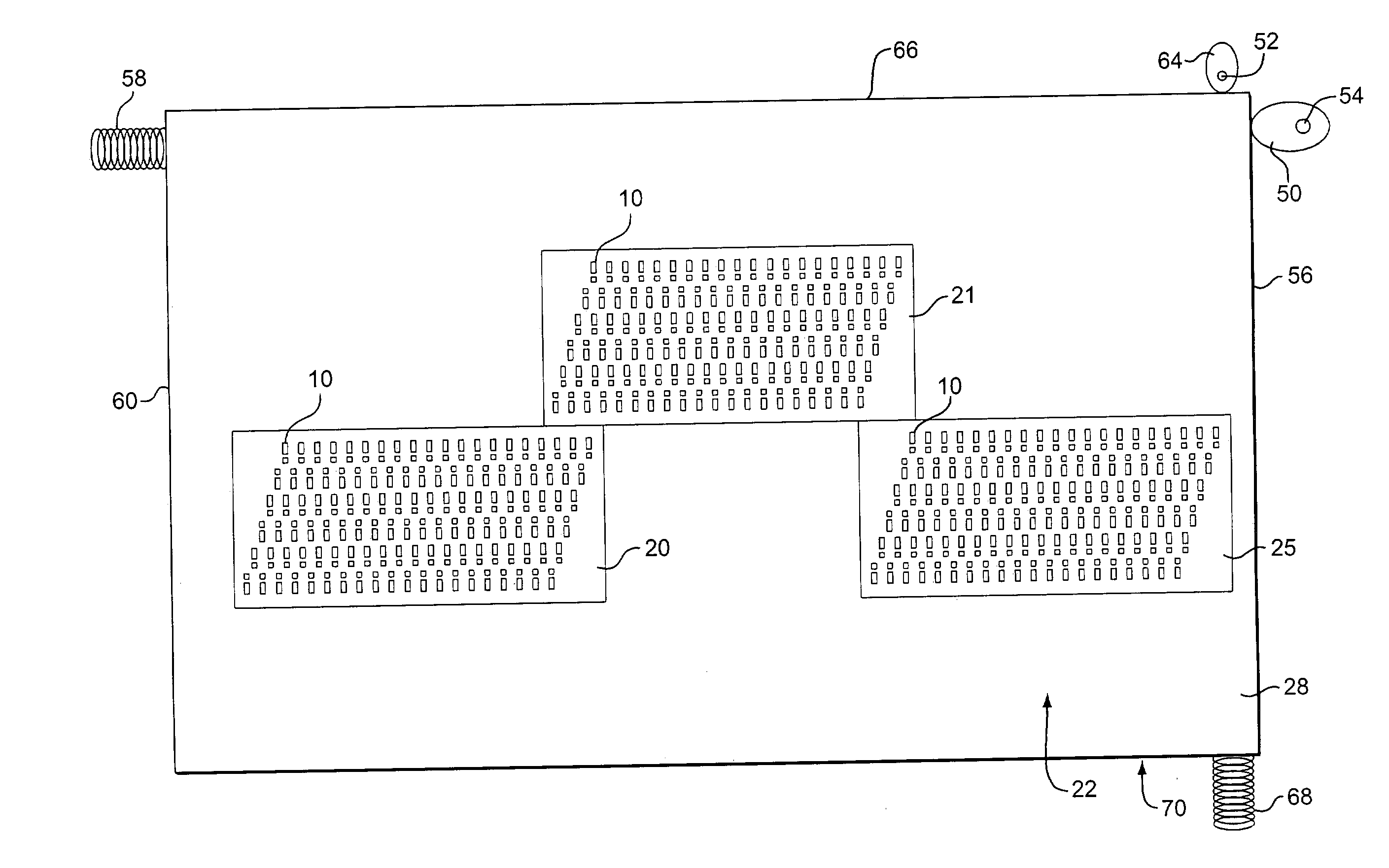
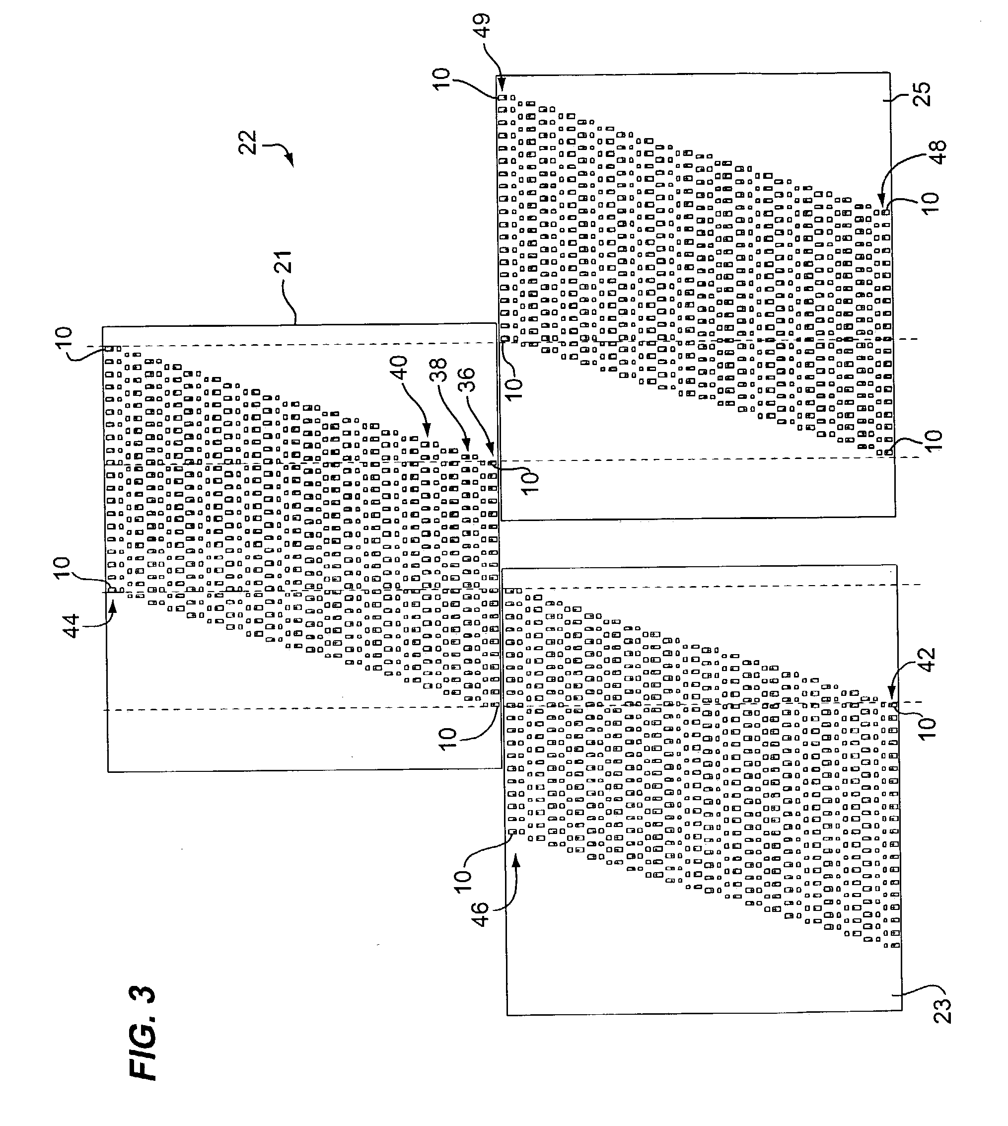
[0034]Referring now to FIG. 2, there is illustrated therein a building block 20 having a first array 21 of the UV LED assemblies 10 thereon, namely, pads 12 and anodes 14, which provide a plurality of UV LED chips 16. The building block 20 is designed to mate with similar building blocks to form a group 22 of arrays 21, 23 and 25 as shown in FIGS. 3 and 4. In this way, several of the blocks 20 can matingly engage each other and be arranged in a pattern (e.g. like tiles on a floor) on a panel 28 (FIG. 4).

[0035]As shown in FIG. 3, the...


PUM

PropertyMeasurementUnit
Timeaaaaaaaaaa
Lengthaaaaaaaaaa
Lengthaaaaaaaaaa

Abstract

A UV curing apparatus and method is provided for enhancing the distribution and application of UV light to UV photo initiators in a UV curable ink, coating or adhesive. The UV curing apparatus and method comprises UV LED assemblies in a first row with the UV LED assemblies spaced from adjacent UV LED assemblies. At least one second row of a plurality of UV LED assemblies are provided next to the first row but with the UV LED assemblies of the second row positioned adjacent the spaces between adjacent UV LED assemblies in the first row thereby to stagger the second row of UV LED assemblies from the UV LED assemblies in the first row. Desirably, the rows of staggered UV LED assemblies are mounted on a panel. UV curable products, articles or other objects containing UV photo initiators that are in or on a web can be conveyed or otherwise moved past the rows of UV LED assemblies for effective UV curing. This arrangement facilitates more uniformly application of UV light on the UV curable ink, coating and/or adhesives in the UV curable products, articles or other objects. The apparatus can include one or more of the following: rollers for moving the web, mechanisms for causing the panel to move in an orbital or reciprocal path, and an injection tube for injecting a non-oxygen gas in the area of UV light curing.

Description

BACKGROUND OF THE INVENTION[0001]1. Field of the Invention[0002]The present invention relates to a method and apparatus for utilizing ultraviolet (UV) light emitting diodes in staggered arrays and mechanisms for moving the arrays to avoid “hot spots” and provide a uniform application of ultraviolet light to a moving object including inks, coatings or adhesives having UV photo initiators for converting, when exposed to UV light, monomers in the inks, coatings or adhesives to linking polymers to solidify the monomer material. Also, an inert, non-oxygen, gas is injected into the area where the staggered arrays of ultraviolet light emitting diodes, UV-LED's are positioned to apply UV light to the moving objects to enhance the curing of the ultraviolet activated UV photo initiators.[0003]2. Description of the Prior Art[0004]Heretofore, ultraviolet lamps have been used for the curing of ultraviolet inks, coatings and adhesives.[0005]More recently, EXFO and EFOS of Mississauga, Ontario, Ca...

Claims


Application Information

Patent Timeline
IPC IPC(8): H01L31/14H05B33/02B05D3/06C08F2/48C08J7/18B41F23/04F26B3/28
CPCF26B3/28B41F23/0409
Inventor SIEGEL, STEPHEN B.
Owner CON TROL CURE
Why Eureka
Try Eureka