
Nanocarpets for trapping particulates, bacteria and spores

a nanocarpet and particulate technology, applied in the direction of electrostatic separation details, diaphragms, electrostatic lysis, etc., can solve the problems of ineffective real-time detectors, inability to achieve, and devices may miss all the other particulates of interest present in the environmen

Inactive Publication Date: 2007-02-13
CALIFORNIA INST OF TECH
View PDF13 Cites 18 Cited by
  • Summary
  • Abstract
  • Description
  • Claims
  • Application Information

AI Technical Summary

Benefits of technology

The present invention is about a new type of nanofeature particulate trap that can detect and trap particles with high efficiency. The trap is made up of densely packed nanofeatures, such as nanotubes, which are designed to have large surface-to-volume ratios, hydrophobicity, and a confined radius of curvature. The nanofeatures can also be actuated by an electrical field or designed to detect molecules. The invention also includes methods for controlling the physical properties of the nanotubes and positioning the trap during growth. The nanotubes can be self-assembled and made from various materials like silicon or carbon. The technical effects of this invention include improved sensitivity and accuracy in particle detection and analysis, as well as improved efficiency in detecting and trapping particles.

Problems solved by technology

However, very often airborne and waterborne microbiological entities, such as macro-biomolecules, spores, bacteria, etc. occur in such low concentrations that real-time detectors are ineffective at sensing them.
In addition, the identification of these particulates often requires some form of intrusive analysis (tagging, DNA extraction, etc.), which cannot be accomplished if the particulate is free to move away from the location of the detector.
Finally, while many of the current nano-sensors are very sensitively tuned to capture and identify one particular species (DNA strands, Salmonella etc.), the devices may miss all the other particulates of interest present in the environment.
However, although high surface area activated charcoal is an excellent trapping material, the three-dimensional nature of the high surface area matrix makes it very difficult to use standard detection schemes, laser diagnostics techniques (UV fluorescence and other non-linear light scattering techniques) to actually distinguish the particles of interest (such as those containing proteins, nucleic acids, and coenzymes) from other organic and inorganic particulate contaminants.

Method used


Image

  • Nanocarpets for trapping particulates, bacteria and spores
  • Nanocarpets for trapping particulates, bacteria and spores
  • Nanocarpets for trapping particulates, bacteria and spores

Examples


Embodiment Construction

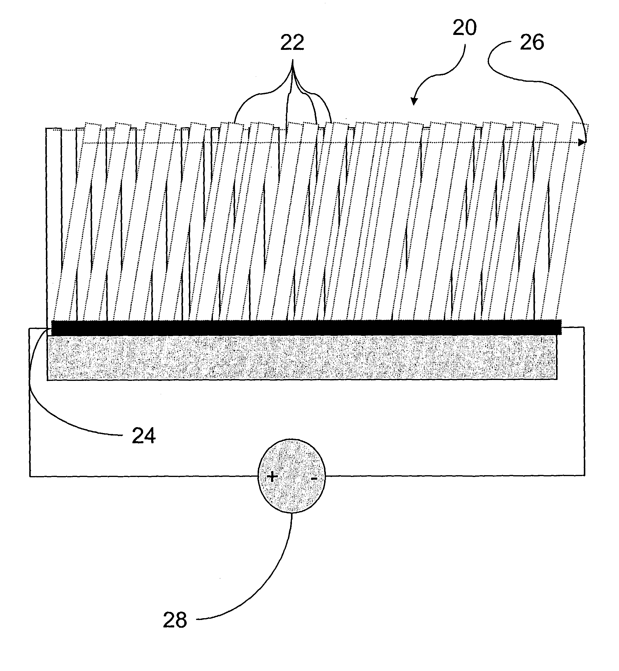
[0034]The present invention is directed to a nanofeature particulate trap comprising a plurality of densely packed nanofeatures, such as nanotubes. The invention is also directed to a particulate detector incorporating the nanofeature particulate trap. These devices will be collectively referred to as nanotraps herein.

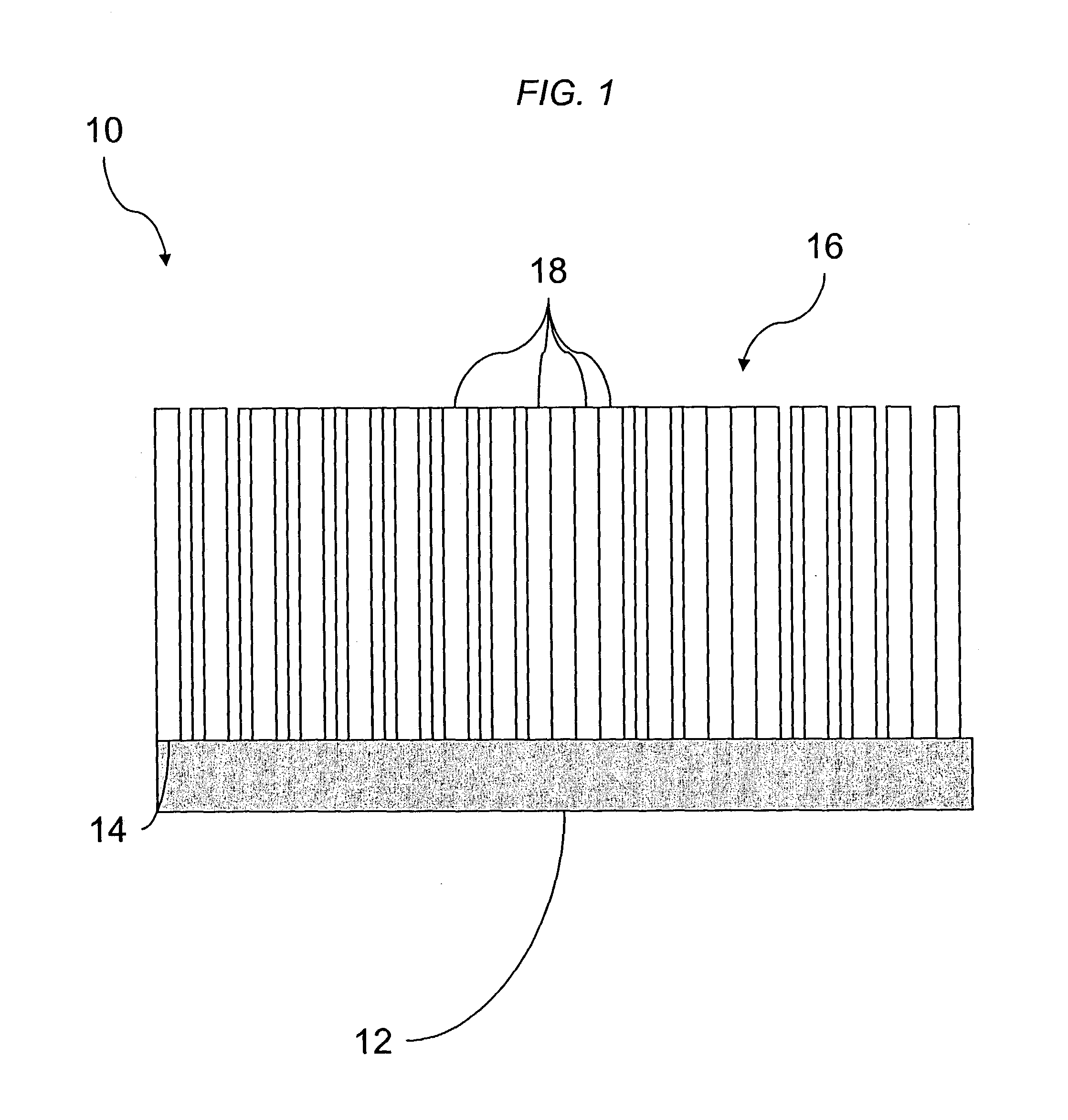
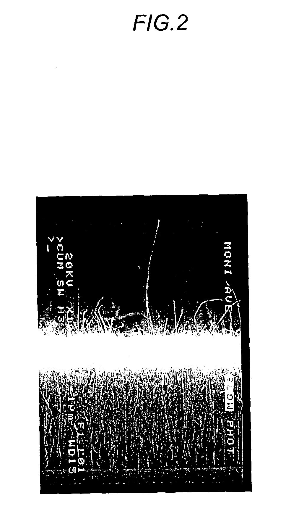
[0035]As shown in FIG. 1, in the most basic embodiment the nanotrap device 10 according to the invention generally comprises a substrate 12, having a growth surface 14 that can additionally be coated with a catalyst to encourage nanofeature growth. A layer 16 of densely packed nanofeatures capable of entrapping particulates of less than 10 microns is then grown on top of the growth surface of the substrate. In the embodiment shown in FIG. 1, the nanofeatures comprise a plurality of nanotubes 18 arranged such that the nanotubes originate and grow normal to the growth surface. Side and top view micrographs of exemplary nanotube nanotraps are shown in FIGS. 2 and 3.

[0036]...


PUM

PropertyMeasurementUnit
diameteraaaaaaaaaa
Young's modulusaaaaaaaaaa
surface-to-volume ratioaaaaaaaaaa

Abstract

A nanofeature particulate trap comprising a plurality of densely packed nanofeatures, such as nanotubes, and a particulate detector incorporating the nanofeature particulate trap are provided. A method of producing a nanotrap structure alone or integrated with a particulate detector is also provided.

Description

CROSS-REFERENCE TO RELATED APPLICATION[0001]This application is based on and claims priority to U.S. Provisional Application No. 60 / 386,526, filed Jun. 6, 2002.STATEMENT REGARDING FEDERALLY SPONSORED RESEARCH[0002]The U.S. Government has certain rights in this invention pursuant to grant No. NAS 7-1407, awarded by the National Aeronautics and Space Administration, Office of Space Science.FIELD OF THE INVENTION[0003]The present invention is directed to the growth of dense mats or carpets of nanotubes, and more particularly to the growth of dense carpets of carbon nanotubes for use in trapping small particles for in-situ detection.BACKGROUND OF THE INVENTION[0004]Nanoscale structures are becoming increasingly important because they provide the basis for devices with dramatically reduced power and mass, while simultaneously having enhanced capabilities, and previous patent applications have disclosed the advantageous use of such nanostructures in a number of different real-time, molecu...

Claims


Application Information

Patent Timeline
Patent Type & Authority Patents(United States)
IPC IPC(8): B01D46/50B01D63/00B01D57/02B01D46/00B01D46/24B01D46/54B01D67/00B01D71/02B01J20/28C12NG01N1/40G01N27/00
CPCB01D39/2055B01D46/0032B01D46/2403B01D46/54B01D67/0072B01D71/021B01J20/28007B82Y30/00B01D39/2068B01D2325/38B01D2257/91B01D2275/206B01D2275/30G01N1/405Y10S977/742Y10S977/725Y10S977/72Y10S977/746B01D2323/08B01D2325/10B01D71/0212B01D2323/081
Inventor NOCA, FLAVIOHUNT, BRIAN D.BRONIKOWSKI, MICHAEL J.HOENK, MICHAEL E.KOWALCZYK, ROBERT S.CHOI, DANIEL S.CHEN, FEI
Owner CALIFORNIA INST OF TECH
Learn More