On-die termination impedance calibration device

a calibration device and impedance technology, applied in the field of on-die termination impedance calibration devices, can solve the problems of difficult optimization of odt impedance, limited number of pulses of signal ‘l_calp’, and limit the number of times by which odt impedance can be recalibrated

Inactive Publication Date: 2007-02-13
SK HYNIX INC
View PDF4 Cites 57 Cited by
  • Summary
  • Abstract
  • Description
  • Claims
  • Application Information

AI Technical Summary

Problems solved by technology

However, since the external calibration enable signal ‘ext_calen’ has a predetermined minimum period of time, there is a limitation in the number of times by which the ODT impedance can be recalibrated.
Also, when temperature, voltage and the like of the semiconductor device rapidly change during a normal operation, a problem described below is caused.
That is, as indicated by mark ‘b’ in FIG. 4, since the generation period of the external calibration enable signal ‘ext_calen’ during a normal operation has been decided, the number of pulses of signal ‘L_calp’ is limited even when temperature, voltage and the like rapidly change, so that it is difficult to optimize an ODT impedance.

Method used


Image

  • On-die termination impedance calibration device
  • On-die termination impedance calibration device
  • On-die termination impedance calibration device

Examples


Embodiment Construction

[0046]Hereinafter, a preferred embodiment of the present invention will be described with reference to the accompanying drawings. In the following description and drawings, the same reference numerals are used to designate the same or similar components, and so repetition of the description on the same or similar components will be omitted.

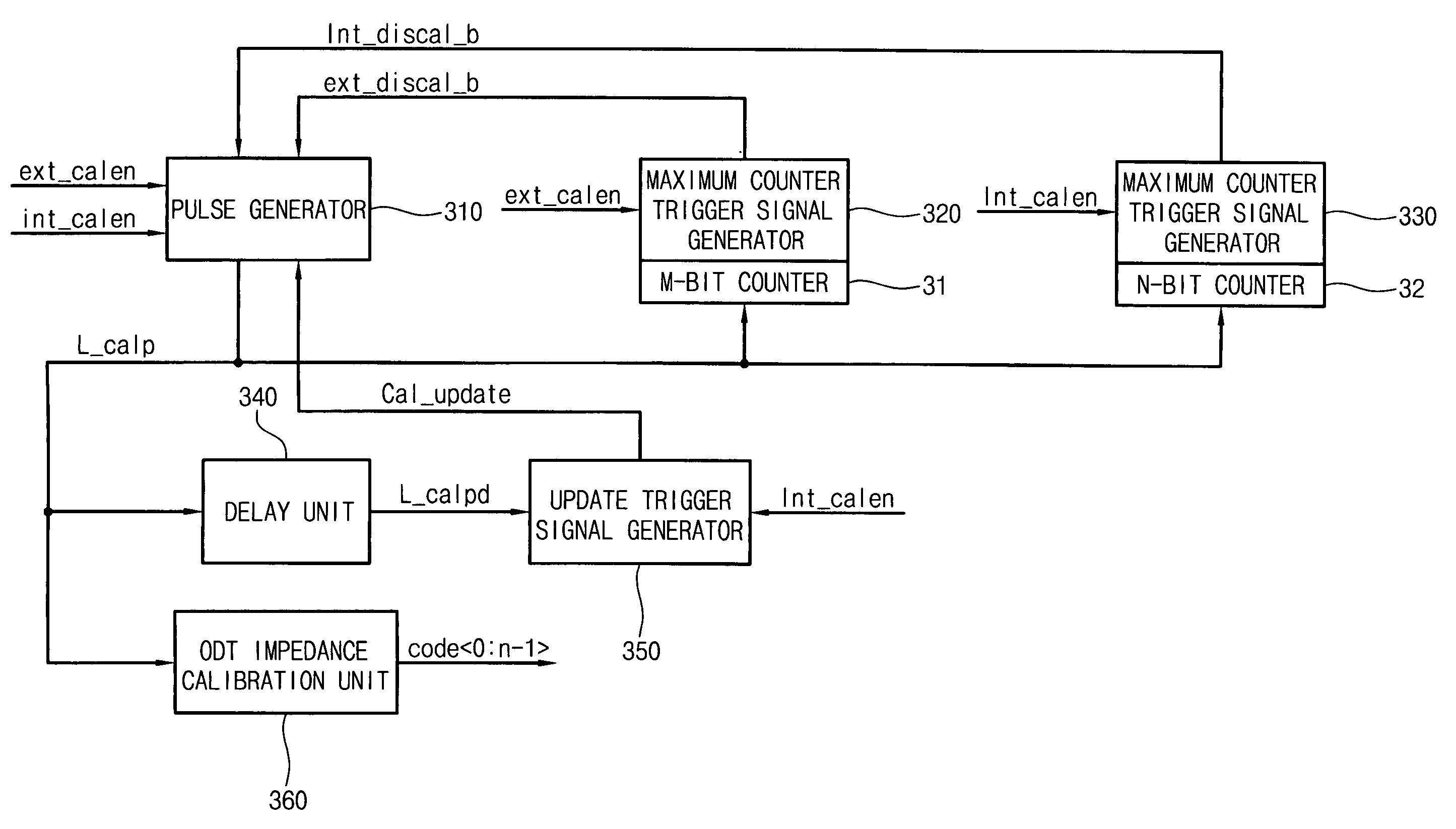
[0047]FIG. 5 is a block diagram illustrating an ODT (on-die termination) impedance calibration device according to an embodiment of the present invention. The ODT impedance calibration device includes a pulse generator 310, maximum counter trigger signal generators 320 and 330, an M-bit counter 31, an N-bit counter 32, a delay unit 340, an update trigger signal generator 350, and an ODT impedance calibration unit 360.

[0048]Herein, an internal calibration enable signal ‘int_calen’ is generated from the interior of a semiconductor device in order to perform an ODT impedance calibration mode.

[0049]An external calibration enable signal ‘ext_calen’ is ...


PUM


Abstract

Disclosed is an on-die termination (‘ODT’) impedance calibration device. The ODT impedance calibration device comprises: a pulse generator for outputting a calibration signal of a pulse type for calibrating an ODT impedance; an M-bit counter for counting the number of pulses of the calibration signal; a first maximum counter trigger signal generator controlled by the M-bit counter; an N-bit counter for counting the number of pulses of the calibration signal; a second maximum counter trigger signal generator controlled by the N-bit counter; a delay unit for receiving a delay signal and outputting the delay signal after a predetermined period of time; an update trigger signal generator for outputting a pulse signal which is toggled according to an output signal of the delay unit; and an ODT impedance calibration unit for receiving the calibration signal and outputting a control signal for calibrating an ODT impedance.

Description

BACKGROUND OF THE INVENTION[0001]1. Field of the Invention[0002]The present invention relates to an on-die termination impedance calibration device, and more particularly to an on-die termination impedance calibration device which is insensitive to the process environment, voltage environment and temperature environment, and can perform the calibration according to its own path and its own schedule.[0003]2. Description of the Prior Art[0004]In general, when a pulse or a signal (hereinafter, referred to as “signal”) is transferred from a bus line to another bus line, a portion of the transferred signal is reflected if impedances of the bus lines are not matched to each other. An on-die termination (hereinafter, referred to as “ODT”) technique is used to reduce such reflection of the signal.[0005]A semiconductor device such as a memory device transmits / receives data and the like to / from an exterior system. When an impedance of a bus line connected between a semiconductor device and an...

Claims


Application Information

Patent Timeline
Patent Type & Authority Patents(United States)
IPC IPC(8): H03K17/16G01R35/00H03K19/003G11C7/10H04L25/02
CPCH04L25/0278E03C1/14A47K10/485A47K7/02
Inventor PARK, NAK KYUCHO, SEONG IK
Owner SK HYNIX INC
Why Eureka
Try Eureka