Compact radio equipment and method of mounting the same

a radio equipment and compact technology, applied in the direction of electrical apparatus construction details, casings/cabinets/drawers, casings/cabinets/drawers details, etc., can solve the problems of reducing workability, preventing the achievement of small radio equipment design, and prone to damage of hooked parts, so as to improve electrical, mechanical and heat measures, the effect of small equipment design

Inactive Publication Date: 2007-02-13
LENOVO INNOVATIONS LTD HONG KONG
View PDF21 Cites 53 Cited by
  • Summary
  • Abstract
  • Description
  • Claims
  • Application Information

AI Technical Summary

Benefits of technology

[0010]It is therefore an object of the present invention to provide compact radio equipment and its mounting method, which can connect two or more printed circuit boards and mount them in the equipment in such an efficient manner that can achieve a small, thin equipment design, improve electrical, mechanical, and heat measures, and enable cost cutting.

Problems solved by technology

The increased thickness of the frame is the cause of preventing the achievement of a small, thin radio equipment design.
The use of screws to secure the second printed circuit board requires an additional step of attaching the screws at manufacturing facilities, and this reduces workability.
On the other hand, the use of hooks to secure the second printed circuit board causes another problem that the hooked portions are susceptible to damage.
The die cast alloy is suitable for making the equipment small and thin, but manufacturing costs are high.
Further, the use of a connector or pin contact system to electrically connect the electric circuits on the first printed circuit board and the electric circuits on the second printed circuit board is not enough to supply adequate ground potential.
However, since aluminum deposition is expensive, the cost of a resin molded frame with aluminum deposited on it becomes high.
Further, since the resin molded frame with aluminum deposited on it is of a contact type, adequate conductivity cannot be obtained.
In this case, since not only is the supply of the ground potential inadequate, but the thermal conductivity is also insufficient, heat may be built up in a local place.

Method used


Image

  • Compact radio equipment and method of mounting the same
  • Compact radio equipment and method of mounting the same
  • Compact radio equipment and method of mounting the same

Examples


first embodiment

[0046](First Embodiment)

[0047]Subsequently, description will be made of a first embodiment of the present invention.

[0048](Structure of First Embodiment)

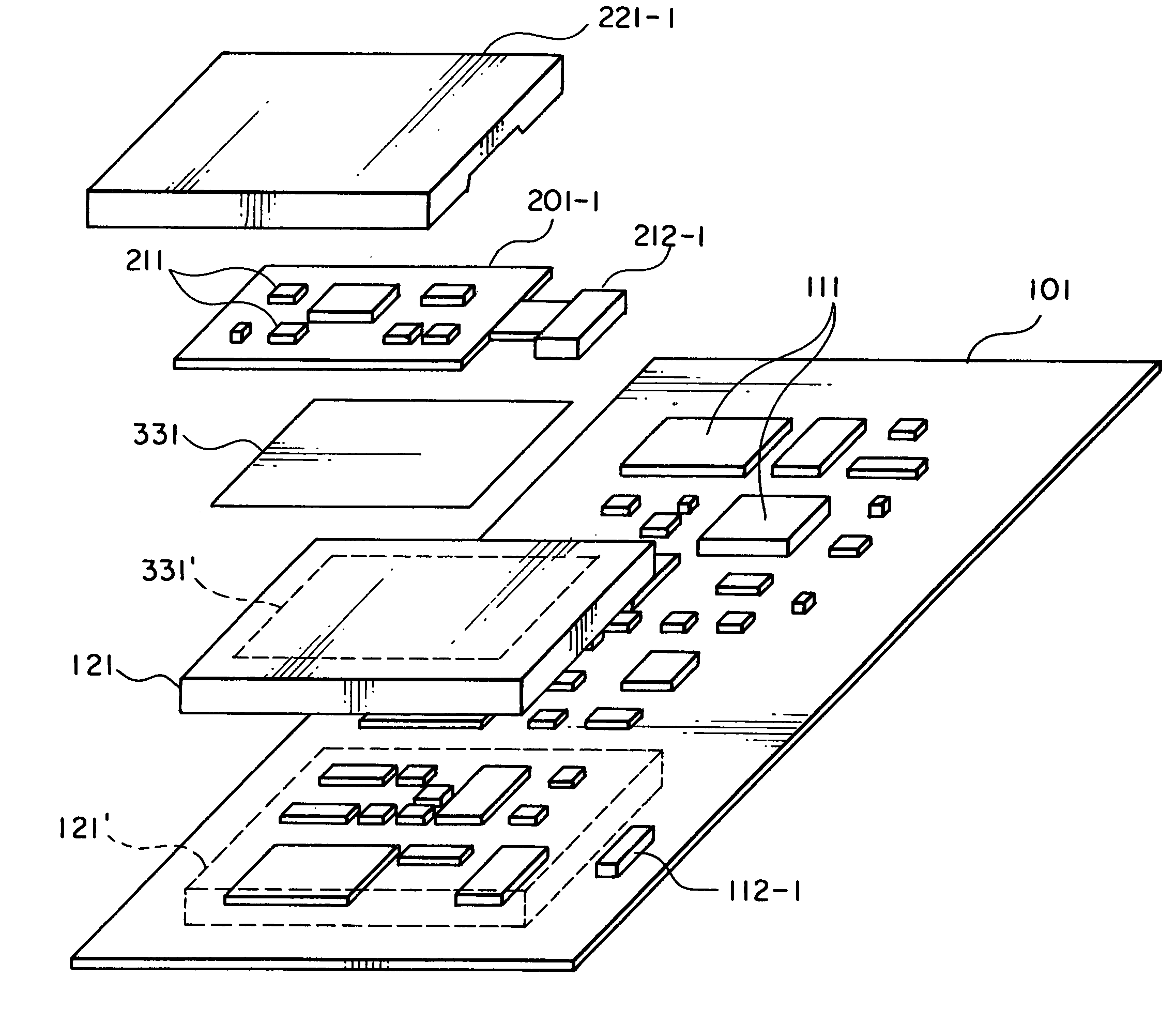
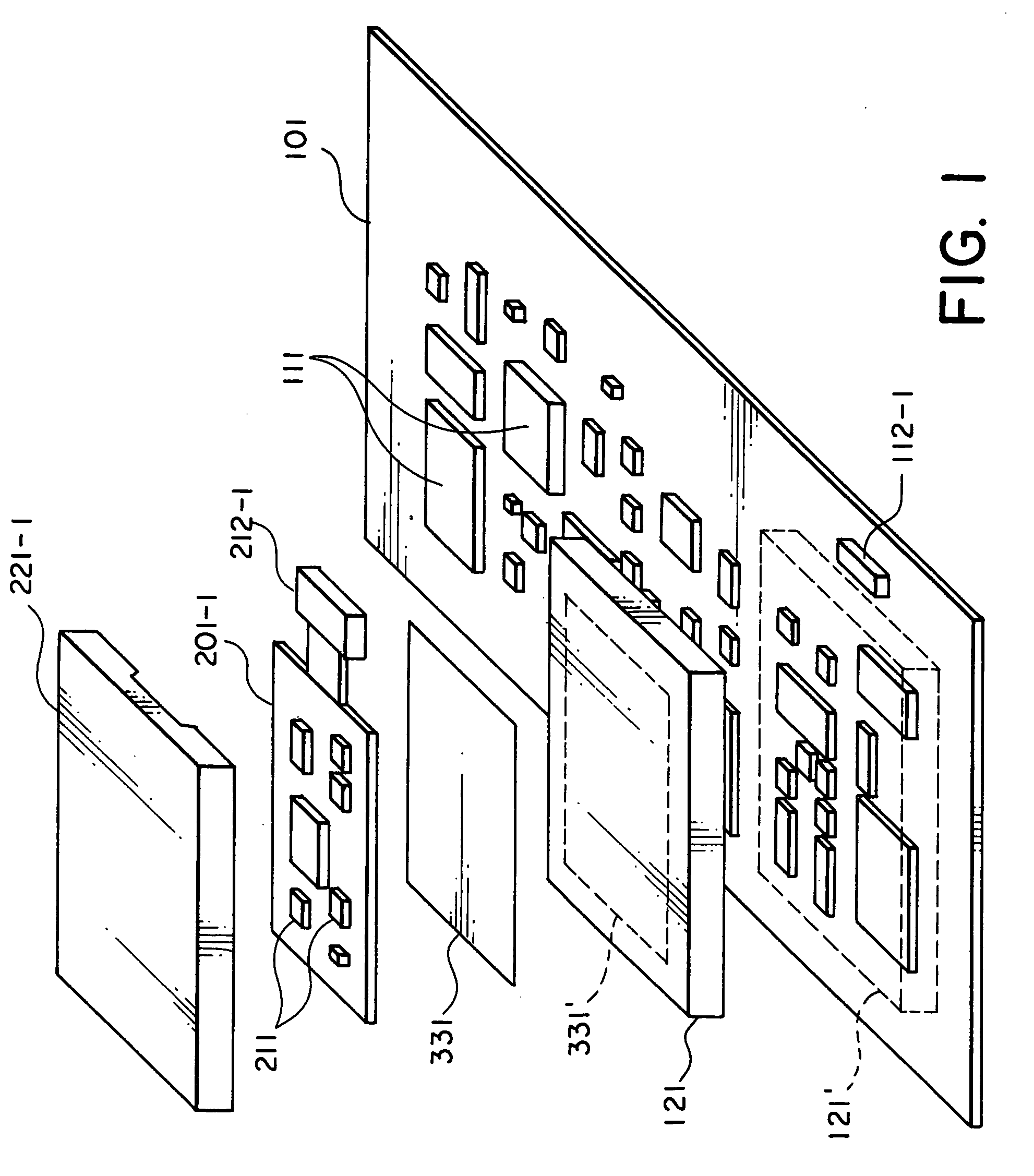
[0049]As shown in FIG. 1, the compact radio equipment according to the present invention includes the first printed circuit board 101, the first electric circuits 111, the first shield frame 121, the second printed circuit board 201-1, the second electric circuits 211, the second shield frame 221-1, the connector 112-1, the receptor 212-1, and the jointing material 331.

[0050]In addition to these circuit components, the compact radio equipment shown in FIG. 1 is made up of a main-unit case 1, an antenna 2, a battery 3, switches 4, a display 5, etc.

[0051]In FIG. 1, the first electric circuits 111 and the second electric circuits 211 are electric circuits of the compact radio equipment, and they are divided into blocks and mounted on two or more printed circuit boards due to limitations on mounting size and electrical properties.

[0052]...

second embodiment

[0098](Second Embodiment)

[0099]Subsequently, description will be made of a second embodiment of the present invention.

[0100](Structure of Second Embodiment)

[0101]In FIG. 6, similar members to those shown in the first embodiment are used for the first printed circuit board 101, the first electric circuits 111, the first shield frame 121, the second printed circuit board 201-1, the second electric circuits 211, a second shield frame 221-2, a connector 112-2, and the jointing material 331.

[0102]In the first embodiment, the second shield frame 221-1 is mounted on the first shield frame 121. On the other hand, in the second embodiment, the second shield frame 221-2 is mounted on the first printed circuit board 101 as shown in FIGS. 6 and 7 to cover the first shield frame 121 and the connector 112-2 together with the second printed circuit board 201-1 with the second electric circuits 211 mounted on it. Indicated by dashed lines 221′ in FIG. 6 is the mounting location of the second shield...

third embodiment

[0117](Third Embodiment)

[0118]Subsequently, description will be made of a third embodiment of the present invention.

[0119](Structure of Third Embodiment)

[0120]Referring to FIG. 9, description will be made of a structure of a third embodiment according to the present invention.

[0121]In FIG. 9, similar members to those shown in the first embodiment are used for the first printed circuit board 101, the first electric circuits 111, the first shield frame 121, a second printed circuit board 201-2, the second electric circuits 211, a second shield frame 221-3, the connector 112-1, the receptor 212-1, and the jointing material 331.

[0122]In the first embodiment, the second shield frame 221-1 is mounted on the top plate of the first shield frame 121 in such a manner to cover the second electric circuits 211 and the second printed circuit board 201-1. On the other hand, in the third embodiment shown in FIGS. 9 and 10, the second shield frame 221-3 is mounted on the second printed circuit boar...


PUM


Abstract

A compact radio equipment includes internal circuits on two or more printed circuit boards electrically connected to each other and securely mounted in structure. With this structure, a first metal shield frame is mounted on a first printed circuit board to cover components mounted on the first printed circuit board. A second printed circuit board is mounted on the first metal shield frame.

Description

[0001]This application claims priority to prior application JP 2003-313493, the disclosure of which is incorporated herein by reference.BACKGROUND OF THE INVENTION [0002]The present invention relates to a compact radio equipment such as a cell phone or radio communication terminal, and a mounting method thereof.[0003]Conventionally, when electric circuits divided into two or more blocks and mounted on two or more printed circuit boards are mounted in the equipment, a first printed circuit board and a second printed circuit board are electrically connected using one of various kinds of connectors or pin contact systems. A frame is mounted between the first and second printed circuit boards not only to protect the electric circuits on the first printed circuit board, but also position and fix the second printed circuit board (see JP-A-2001-111232).[0004]The conventional frame mentioned above is molded of resin, or made from die cast alloy. The second printed circuit board is secured w...

Claims


Application Information

Patent Timeline
Patent Type & Authority Patents(United States)
IPC IPC(8): H05K9/00H04B15/00H05K1/14H05K3/00
CPCH04B15/00H05K1/141H05K9/0039H05K2201/10371H05K3/0061
Inventor SHIMA, MAKOTO
Owner LENOVO INNOVATIONS LTD HONG KONG
Why Eureka
Try Eureka