Compact radio equipment and method of mounting the same

a radio equipment and compact technology, applied in the direction of electrical apparatus construction details, casings/cabinets/drawers, casings/cabinets/drawers details, etc., can solve the problems of reducing workability, preventing the achievement of small radio equipment design, and prone to damage of hooked parts, so as to improve electrical, mechanical and heat measures, the effect of small equipment design

Inactive Publication Date: 2005-03-10
LENOVO INNOVATIONS LTD HONG KONG
View PDF20 Cites 35 Cited by
  • Summary
  • Abstract
  • Description
  • Claims
  • Application Information

AI Technical Summary

Benefits of technology

[0010] It is therefore an object of the present invention to provide compact radio equipment and its mounting method, which can connect two or more printed circuit boards and mo

Problems solved by technology

The increased thickness of the frame is the cause of preventing the achievement of a small, thin radio equipment design.
The use of screws to secure the second printed circuit board requires an additional step of attaching the screws at manufacturing facilities, and this reduces workability.
On the other hand, the use of hooks to secure the second printed circuit board causes another problem that the hooked portions are susceptible to damage.
The die cast alloy is suitable for making the equipment small and thin, but manufacturing costs are high.
Further, the use of a connector or pin contact system to elec

Method used


Image

  • Compact radio equipment and method of mounting the same
  • Compact radio equipment and method of mounting the same
  • Compact radio equipment and method of mounting the same

Examples


first embodiment

Operation of First Embodiment

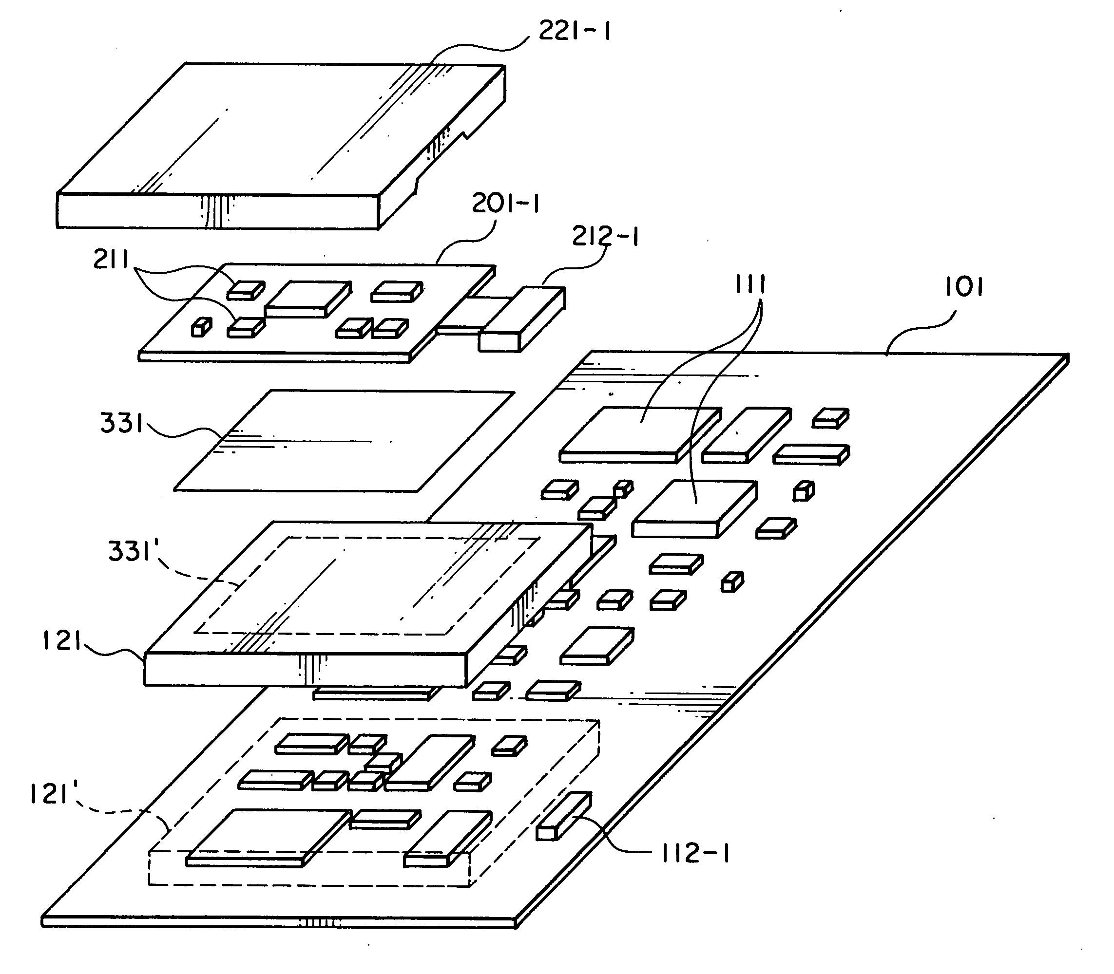
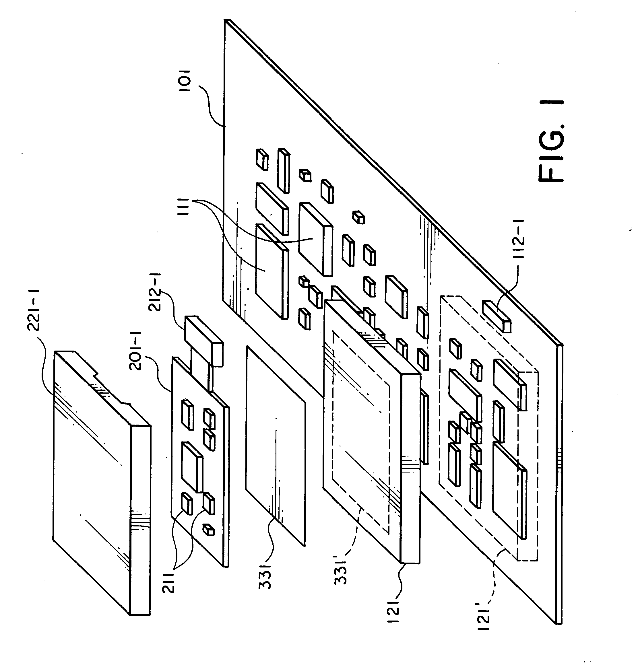
[0066] As shown in FIG. 4, the compact radio equipment includes the printed circuit boards 101, 201-1 as a structure for its electric circuitry, the main-unit case 1, the antenna 2, the battery 3, the switches 4, and the display part 5. In addition, other unillustrated components, such as a loudspeaker, a vibrator, and a camera, are mounted in the case. Thus, although the compact radio equipment includes lots of components, it must be compact and thin to keep its portability.

[0067] As compact radio terminals grow more sophisticated, the number of parts or components increases. The CPU and its clock frequency also become faster. There is also an increased demand for the compact radio equipment typified by a cell phone to have additional functions, which in turn increases the demand for a technique for mounting both the radio circuits for the cell phone functions and the radio circuits for the additional functions. For example, secondary radio circuits fo...

second embodiment

Operation of Second Embodiment

[0099]FIG. 8 is a block diagram showing the operation and structure of the second embodiment of the present invention.

[0100] Cell phones are a typical example of the compact radio equipment. With the recent speed increase in cell phone systems, equipment with two or more radio circuits has been commercially available to meet the need to use both of conventional and next-generation cell phone systems. Referring to FIG. 8, such compact radio equipment with two or more radio circuits will be described.

[0101] In FIG. 8, a second radio circuit corresponds to one of the second electric circuits 211 of FIG. 6 that are mounted on the second printed circuit board 201-1. The contact terminal area 212-2 and the connector 112-2 of FIG. 8 correspond to the contact terminal area 212-2 and the connector 112-2 of FIG. 6. A control electric circuit, a charger electric circuit, a clock electric circuit, and a first radio circuit of FIG. 8 correspond to the electric cir...

third embodiment

Operation of Third Embodiment

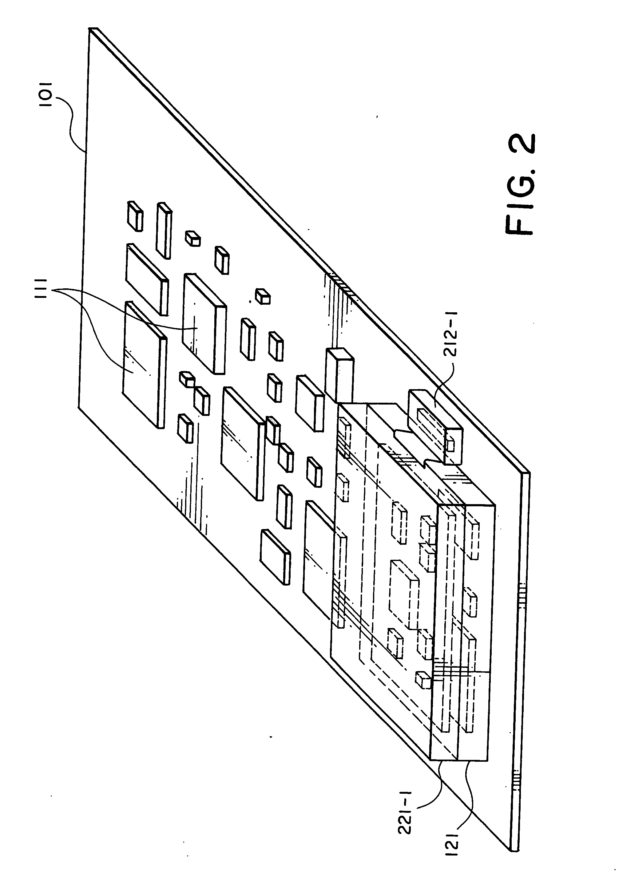
[0116] The first shield frame 121 of conductive metal shields electromagnetic wave noise, so that not only can the radiation of noise from the first electric circuits 111 be reduced, but the influence of noise from the outside can also be reduced. The first shield frame 121 is soldered to the first printed circuit board 101. In this manner, both the radiation of noise and the noise interference can be suppressed. In this event, solder joints are formed to have ground potential. Therefore, if the area of the solder joints is increased, the first shield frame 121 can have the same ground potential as the first printed circuit board 101, and consequently, it can be more resistant to the radiation and interference of noise. This makes it possible not only to stabilize the action of the electric circuits and improve their properties, but also to further improve thermal conductivity and heat radiation efficiency. Moreover, the first shield frame 121 is mechani...


PUM


Abstract

A compact radio equipment includes internal circuits on two or more printed circuit boards electrically connected to each other and securely mounted in structure. With this structure, a first metal shield frame is mounted on a first printed circuit board to cover components mounted on the first printed circuit board. A second printed circuit board is mounted on the first metal shield frame.

Description

[0001] This application claims priority to prior application JP 2003-313493, the disclosure of which is incorporated herein by reference. BACKGROUND OF THE INVENTION [0002] The present invention relates to a compact radio equipment such as a cell phone or radio communication terminal, and a mounting method thereof. [0003] Conventionally, when electric circuits divided into two or more blocks and mounted on two or more printed circuit boards are mounted in the equipment, a first printed circuit board and a second printed circuit board are electrically connected using one of various kinds of connectors or pin contact systems. A frame is mounted between the first and second printed circuit boards not only to protect the electric circuits on the first printed circuit board, but also position and fix the second printed circuit board (see JP-A-2001-111232). [0004] The conventional frame mentioned above is molded of resin, or made from die cast alloy. The second printed circuit board is se...

Claims


Application Information

Patent Timeline
IPC IPC(8): H04B15/00H05K1/14H05K3/00H05K9/00
CPCH04B15/00H05K1/141H05K2201/10371H05K9/0039H05K3/0061
Inventor SHIMA, MAKOTO
Owner LENOVO INNOVATIONS LTD HONG KONG
Why Eureka
Try Eureka