Graphic processing method and device
a graphic processing and program recording technology, applied in image analysis, image enhancement, instruments, etc., can solve the problems of ineffective method, affecting the quantization of the difference between the figures, and difficult to determine statistical significance concerning the differen
- Summary
- Abstract
- Description
- Claims
- Application Information
AI Technical Summary
Benefits of technology
Problems solved by technology
Method used
Image
Examples
first embodiment
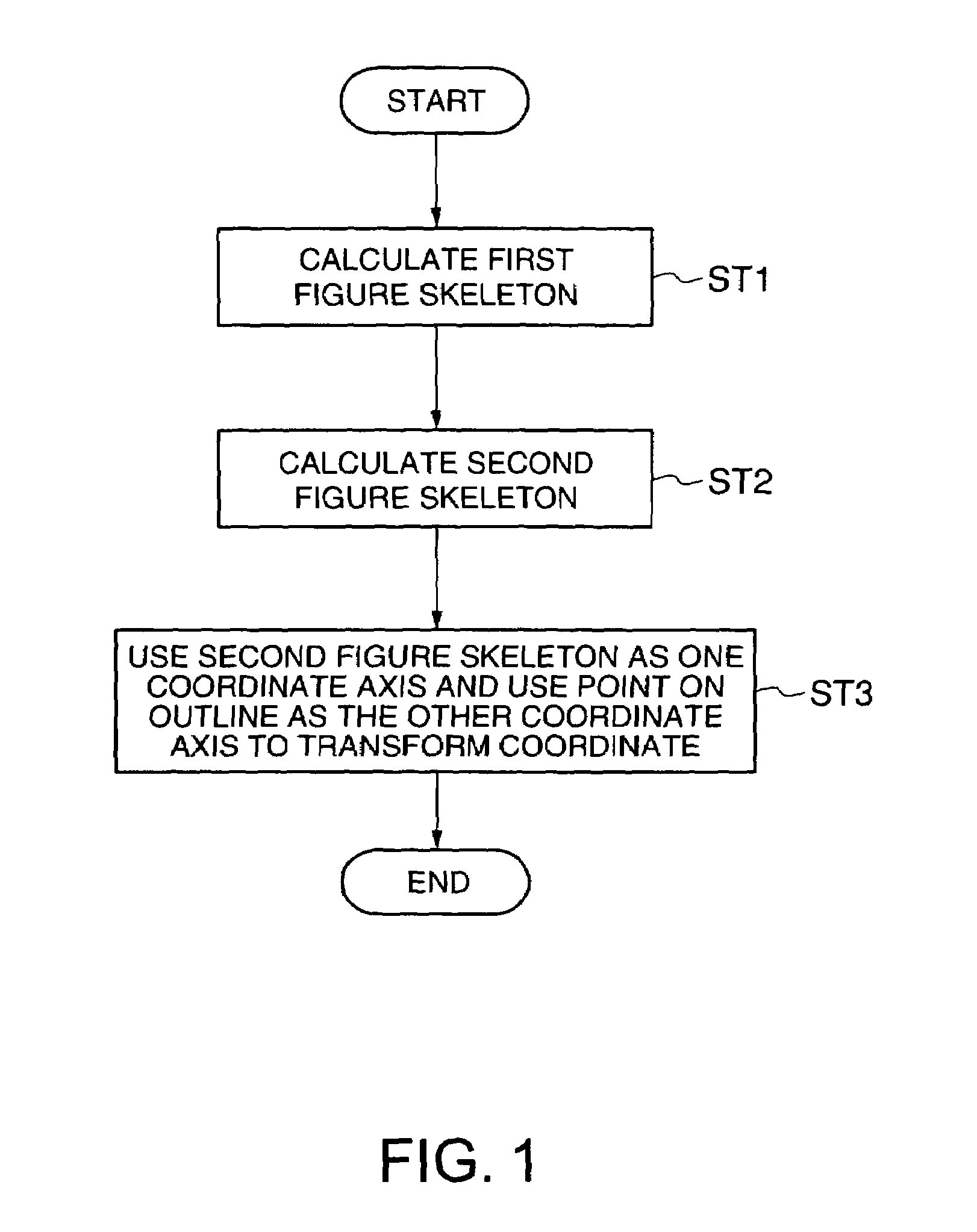
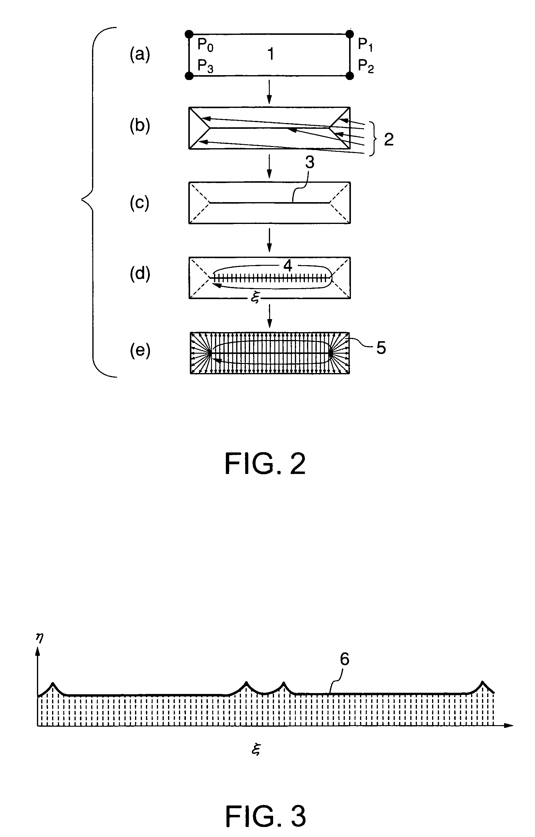
[0037]First, a basic constitution of a graphic processing method according to a first embodiment of the present invention will be described. In the graphic processing method according to a basic constitution, in a first step ST1, a first figure skeleton distant from an outline of a figure by each equal distance toward a center of the figure is calculated using at least one of a medial axis and a chordal axis with respect to the figure in which the outline of an object shape reflected in a digital image is represented by a set of points. Next, in a second step ST2, a branch line extending to the skeleton from a vertex of the figure is deleted from the first figure skeleton calculated by the first step ST1 to obtain a second figure skeleton. Next, in a third step ST3, with respect to data obtained by one circulation of the outline of the figure using one end point of the second figure skeleton obtained by the second step as a start point and using the other end point as a terminal poi...
second embodiment
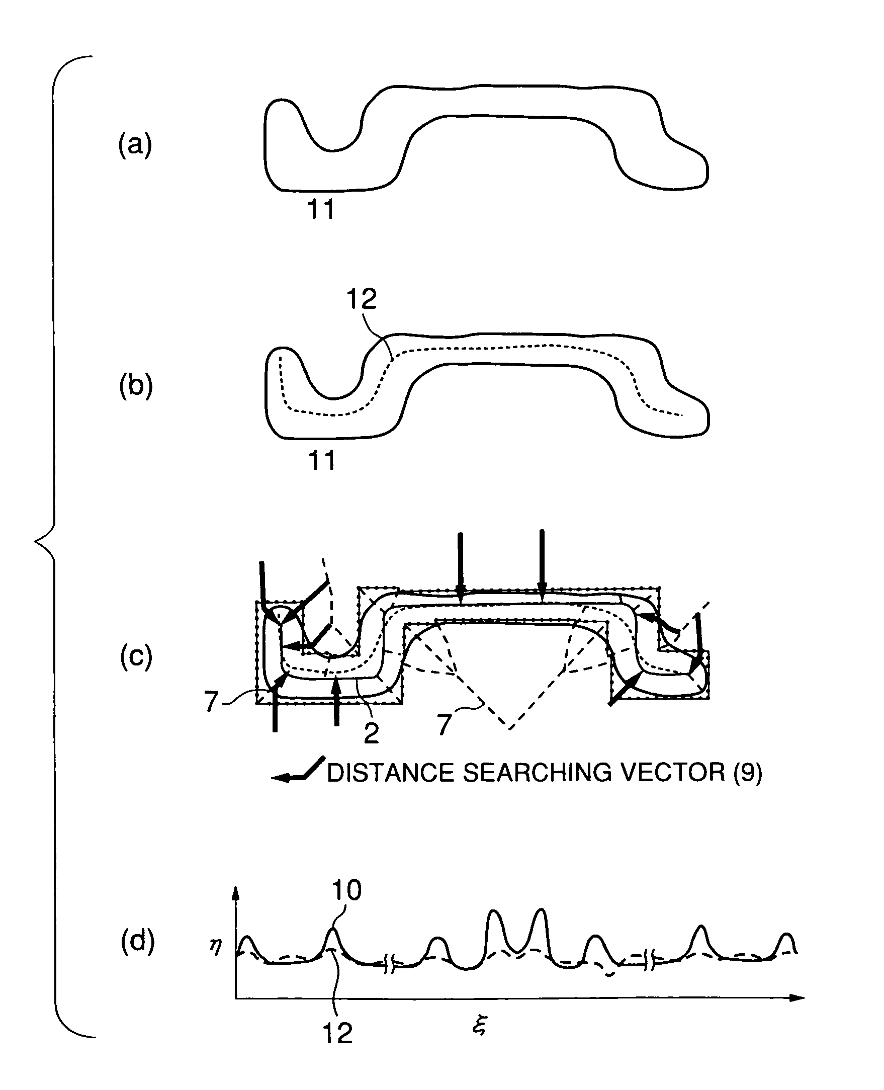
[0050]Next, a graphic processing method according to a second embodiment of the present invention will be described. In the second embodiment, comparison of a CAD figure with an outline figure of a pattern extracted from a SEM image will be described. First, a pattern figure corresponding to a pattern constituting an inspection object is selected from design CAD data, and recorded as polygon data in the storage section 106 of FIG. 19 described later. This figure has a shape shown by a FIG. 14 in FIG. 8(a).
[0051]Subsequently, a medial axis is prepared with respect to this figure, and branches are pruned off from the figure as shown in FIG. 8(b). Next, one end of a skeleton 10 is used as a start point, and a new coordinate is defined as a coordinate axis ξ on a line in a direction of one circulation around the skeleton (11 of FIG. 8(c)). Subsequently, a curve group 13 conjugated with curve groups 12 and 13 at an equal distance from the coordinate axis ξ is calculated to prepare a new ...
third embodiment
[0058]Next, a graphic processing method according to a third embodiment of the present invention will be described. In the third embodiment, a method of evaluation of agreement between two figures will be described. Values obtained by integrating both curves in the ξ-η coordinate system obtained in the second embodiment along ξ are plotted in the ordinate, and ξ is plotted in the abscissa as shown in FIG. 11. Since a maximum value of a difference between the values of both curves normalized as ∫ηdξ=1 in the corresponding ξ coordinate corresponds to Kolmogorov-Smirnov statistic, the values are compared with a numerical table to calculate the agreement between the curves.
PUM
 Abstract
Description
Claims
Application Information
 - R&D
- Intellectual Property
- Life Sciences
- Materials
- Tech Scout
- Unparalleled Data Quality
- Higher Quality Content
- 60% Fewer Hallucinations
Browse by: Latest US Patents, China's latest patents, Technical Efficacy Thesaurus, Application Domain, Technology Topic, Popular Technical Reports.
© 2025 PatSnap. All rights reserved.Legal|Privacy policy|Modern Slavery Act Transparency Statement|Sitemap|About US| Contact US: help@patsnap.com


