Method for calculating power flow solution of a power transmission network that includes unified power flow controllers

a technology of power transmission network and power flow controller, which is applied in the direction of electric variable regulation, process and machine control, instruments, etc., can solve the problems of reducing the reliability of the power transmission network, unbalanced loading of the first and second transmission lines, and difficult to implement the approach in practice, so as to reduce reduce the convergence characteristics of the solution to the power flow equation. , the effect of reducing the number of state variables

Inactive Publication Date: 2007-02-13
CHANG GUNG UNIVERSITY
View PDF6 Cites 48 Cited by
  • Summary
  • Abstract
  • Description
  • Claims
  • Application Information

AI Technical Summary

Benefits of technology

[0075]A further object of this invention is to provide a method for calculating power flow solution of a power transmission network that includes unified power flow controllers, in which, instead of using the voltage magnitudes and the phase angles of the shunt converter and the series converter as the state variables as in the prior art, the orthogonal current components of a shunt voltage source in an equivalent static model are used as the state variables, such that the effect of the selection of the initial values of the state variables on the convergence characteristics of the solution to the power flow equation can be minimized.
[0132]The effects of this invention reside in that consideration is given to the active power losses of the transformers and converters in the unified power flow controller at the same time, and that the series converter and the shunt converter are set according to the calculated voltages of the series voltage source and the shunt voltage source as parameters. Therefore, this invention can achieve control objective values with higher precision than the prior art. In addition, because the direct-axis and quadrature-axis components of the output current of the shunt voltage source in the equivalent static model are used as the state variables in place of the voltage magnitudes and phase angles of the shunt converter and series converter in the prior art, not only can the number of state variables be decreased, the effect of the selection of the initial values of the state variables on the convergence characteristics of the solution to the power flow equation can be reduced as well. In addition, the method for calculating power flow solution of a power transmission network that includes unified power flow controllers is suited for application to a unified power flow controller which is operable in different operating modes, while ensuring good convergence characteristics under different control objectives.

Problems solved by technology

If the power transmission capacities of the first transmission line 821 and the second transmission line 822 are different, the power flow will be distributed according to the impedance characteristics of the two transmission lines 821, 822, thereby resulting in unbalanced loading of the first and second transmission lines.
Such a situation of unbalanced loading of the first and second transmission lines 821, 822 will reduce the reliability of the power transmission network.
However, such an approach is difficult to implement in practice since the first transmission line 821 may be as long as tens or hundreds of miles.
Furthermore, the aforesaid conventional approach can only be adapted for use when the shunt converter 74 and the series converter 72 are operated in specific operating modes.

Method used


Image

  • Method for calculating power flow solution of a power transmission network that includes unified power flow controllers
  • Method for calculating power flow solution of a power transmission network that includes unified power flow controllers
  • Method for calculating power flow solution of a power transmission network that includes unified power flow controllers

Examples


Embodiment Construction

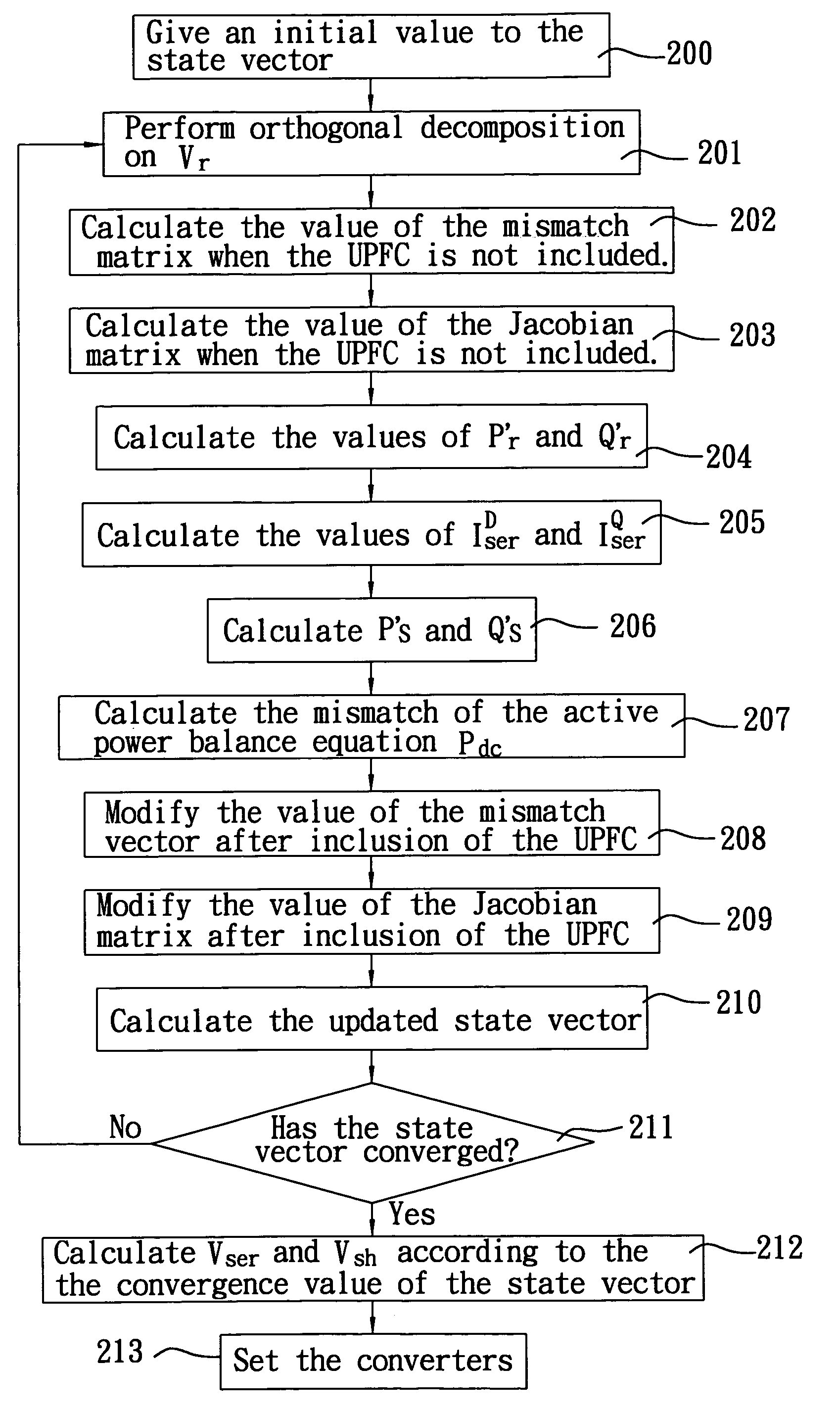
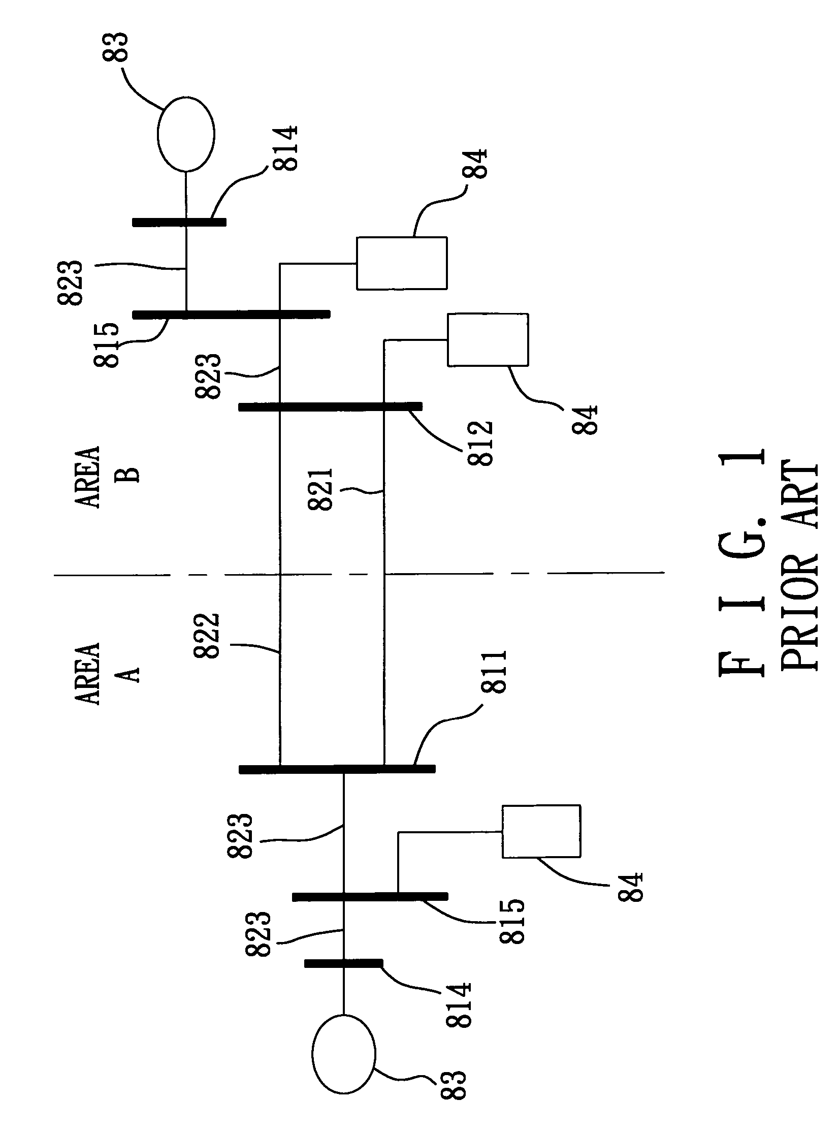
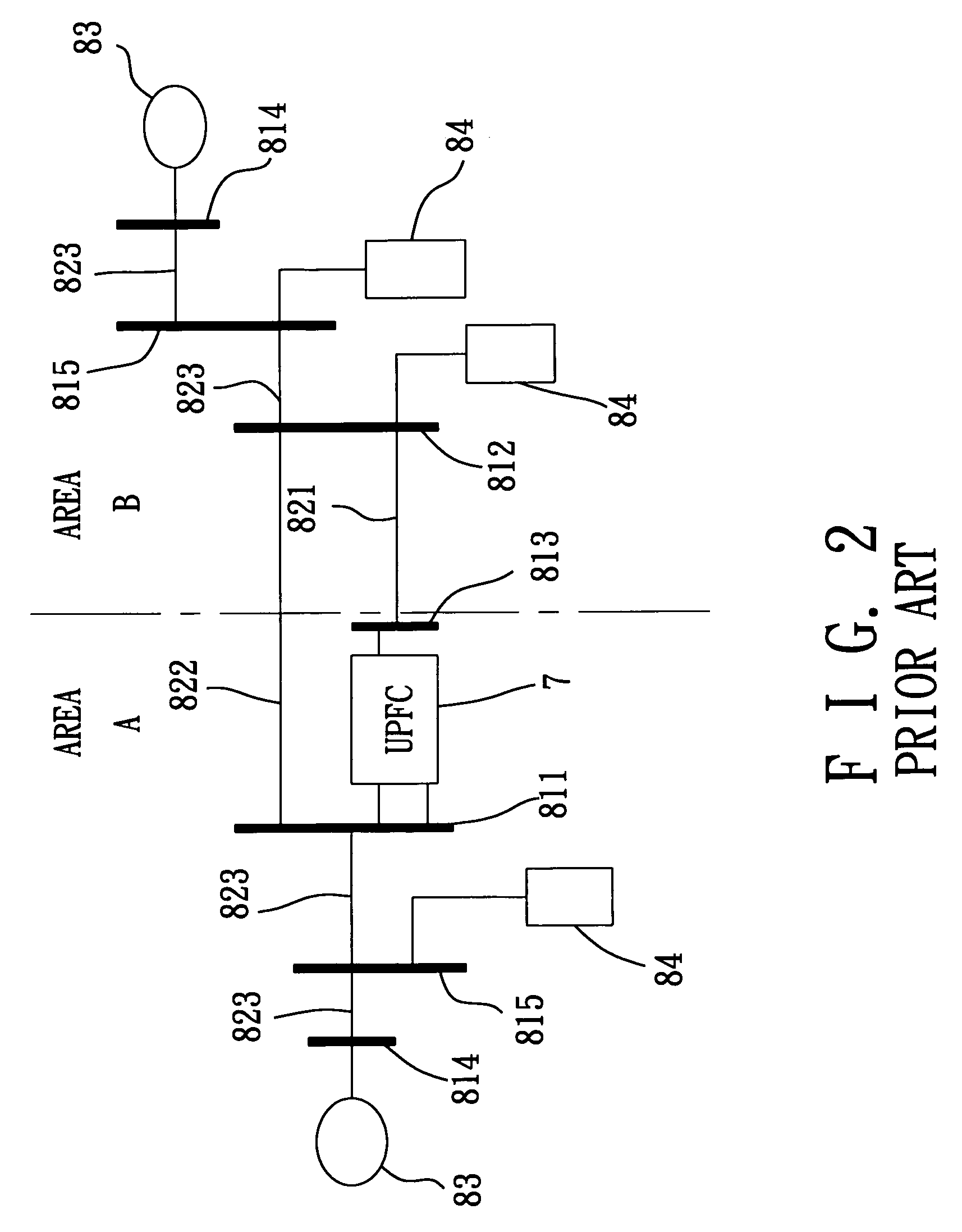
[0141]Referring to FIGS. 2 and 7, the power flow calculating method of this invention is adapted for application to a power transmission network that includes unified power flow controllers. The power transmission network includes a sending-end bus 811, a receiving-end bus 813, a demand-end bus 812, a first transmission line 821, a second transmission line 822, a plurality of transmission lines 823, a plurality of power generating devices 83, and a plurality of load devices 84. In addition, the power transmission network has a UPFC 7 installed therein. Since the components of the power transmission network and the connections among the components are identical to those of the prior art, a description thereof is dispensed hereinafter for the sake of brevity.

[0142]Referring to FIG. 3, the UPFC 7 includes a series transformer 71, a series converter 72, a direct current coupling capacitor 73, a shunt converter 74, and a shunt transformer 75. Since the internal elements of the UPFC 7 and...


PUM


Abstract

A method for calculating power flow solution of a power transmission network with unified power flow controllers is adapted to calculate the power flow on a large-scale power transmission network. The unified power flow controller has a series transformer, a series converter, a direct current coupling capacitor, a shunt converter, and a series transformer. The shunt transformer is connected electrically to a sending-end bus. The series transformer is connected electrically to the sending-end bus and a receiving-end bus. The unified power flow controller is represented by equivalent active and reactive loads on the sending-end and receiving-end buses of the power transmission network.

Description

CROSS-REFERENCE TO RELATED APPLICATION[0001]This application claims priority of Taiwanese Application No. 094111122, filed on Apr. 8, 2005.BACKGROUND OF THE INVENTION[0002]1. Field of the Invention[0003]The invention relates to a method for calculating power flow solution of a power transmission network, more particularly to a method for calculating power flow solution of a power transmission network that includes a single or multiple unified power flow controllers.[0004]2. Description of the Related Art[0005]Referring to FIG. 1, a power transmission network interface of a typical power system for two areas is shown to include a sending-end bus 811, a demand-end bus 812, a first transmission line 821, a second transmission line 822, a plurality of transmission lines 823, a plurality of power generator buses 814, a plurality of load buses 815, a plurality of power generating devices 83, and a plurality of load devices 84.[0006]The transmission lines 821–823 in general have specific p...

Claims


Application Information

Patent Timeline
Patent Type & Authority Patents(United States)
IPC IPC(8): H02J3/04G08B21/00
CPCH02J3/00H02J3/1814H02J3/1871Y02E60/76Y02E40/18Y04S40/22H02J2003/007H02J2203/20Y02E40/10Y02E60/00Y04S40/20
Inventor CHU, CHIA-CHILEE, SHENG-HUEITSAI, HUNG-CHI
Owner CHANG GUNG UNIVERSITY
Why Eureka
Try Eureka